14
Sonix Pbx Technical Manual
SONIX PBX TECHNICAL MANUAL
TM372 / A June 2022 www.eaton.com
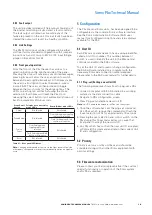
4.2.10 Fuse
This indicates the status of the internal fuse for the
48 V dc input.
Pattern
Description
Solid green
Fuse good
Solid red
Fuse failed
Table 17 – Fuse LED description
4.2.11 DC PSU
This indicates internal power supplies feeding the main
electronic circuit are available.
4.2.12 Switch indications
These four options are available to user by using the
front switch panel. The option are scrolled through by
repeated presses of the front panel switch
(see section 4.8.5)
Pattern
Description
Solid green
(cancel)
Allows the user to cancel a message while recording or
in playback
Solid green
(zonal/global)
Allows the user to switch between using user entered
zones or default zone list
Solid green
(source select)
Allows the user to switch between a 2wire and a 2wire
E&M telephone interface
Solid green
(Reset)
Allows the user to carry out a fault reset on the unit.
Table 18 – Switch LED description
4.3 Calling the unit
4.3.1 2-wire operation
Calling the assigned extension number will allow the
unit to auto answer. The time to answer depends on the
unit’s internal ID and whether any faults are registered
on the unit (see Table 18). The unit’s ID is set at
configuration. Implementations requiring the primary and
secondary unit will have the 2-wire input connected in
parallel with the primary unit ID set to 1.
Unit ID
Time to answer
(no faults)
Time to answer
(with faults)
1
Typically, within 2 rings
Typically, within 6 rings
(delayed answer)
2-31
Typically, within 4 rings
(delayed answer)
Typically, within 8 rings
(delayed answer)
Table 19 – Answering times
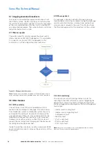
Figure 8 – Primary & Secondary unit interconnection
Once the unit has answered, the user will be instructed
to follow a series of prompts or messages to enter
zoning information or be directed to leave a message
(see sections 4.4 and 4.5).
4.3.2 2-wire E&M operation
Calling the unit with E&M signalling requires no ringing
on the 2-wire audio interface. It will answer on receiving
an active key line on the E&M input of the telephone
interface input. The polarity of the E&M signalling is set
within the unit’s configuration (see the SAS manual for
details).
Once the unit has answered the user will be instructed
to follow a series of prompts or messages to enter
zoning information or be directed to leave a message
(see sections 4.4 and 4.5).
4.3.3 Auto-elevate messages
The unit has the facility to elevate the recorded message
to important message (emergency speech) status by
setting the configuration bit in SAS software.
When this feature is enabled, messages left after the
system has started broadcasting alarms will be given a
higher priority to override the alarm and broadcast the
message. Messages left before an alarm is broadcast
will maintain the lower priority and will not override
the alarm.
4.4 Zoning
The unit can be set to either global or zoned operation
by the front panel control or by loading the correct
configuration into the unit.
The Pbx has the ability to play a custom prompt to help
and guide the user through the available options. Please
contact Eaton for further information.
4.4.1 Global operation
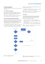
Setting the unit to “global” operation as indicated on
the front panel will cause the unit to bypass the zoning
flow chart (see Figure 8) and prompt the user to leave a
message to be broadcast using the default zone list set
by the unit’s configuration.
R
Sonix Pbx
TM
LOCAL STATUS
POWER SUPPLY
OPERATIONAL
Fuse
Cancel
Zoned / Global
Source Select
Reset
DC PSU
2w
E+M
2w
Global
Message
Zoned
Message
Message
Cancel
Monitor
Active
Pbx
playback
Pbx
record
Power
8
7
6
5
4
3
2
1
Pbx I/P
MONITOR
A SIDE O/P
B SIDE O/P
48V
DC
I/P
+ -
Fault
O/P
N/C
Com
K1 K2 SCN A1 A2
I/O Bus A
I/O Bus B
A1 A2 SCN COM N/C
A1 A2 SCN K1 K2
A1 A2 SCN K1 K2
COMPLIANT
7
6
5
4
3
2
1
2-Wire connection
Screen
E&M connection (optional)
Push button connection
Screen
Loudspeaker connection
Keyline connection
Screen
Audio connection
Power connection
0Vdc (-)
48Vdc (+)
General fault connection
N/C
Com
Pbx I/P
Primary Unit ID 1
Secondary Unit ID 2+
2 wire
Telephone I/F
Pbx I/P
K1 K2 SCN A1 A2
K1 K2 SCN A1 A2


