3
Instruction Booklet
IB158002EN
Effective October 2018
Eaton SPD Max Series
Surge Protective Device
EATON
www.eaton.com
1.5 Equipment Testing
m
WARNING
CONDUCTING DIELECTRIC, MEGGER, OR HI-POTENTIAL TESTING WITH THE
SPD INSTALLED WILL CAUSE INTERNAL DAMAGE TO THE SPD. THE SPD
WILL ALSO CAUSE THE TEST TO FAIL.
Every Eaton SPD Max Series unit is tested at the factory for dielec-
tric breakdown. No further SPD testing is required for installation.
If you desire to test distribution equipment by performing dielectric,
megger, or hi-potential tests, any installed SPD must be discon-
nected from the power distribution system to prevent damage to the
unit.
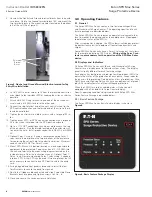
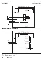
Follow this procedure to safely disconnect the SPD:
1. For SPDs connected to a circuit breaker or fuse:
a. 3-wire Delta SPDs: Turn off the circuit breaker or remove the
fuses from the fuse holder to isolate the SPD.
b. Wye and Split phase SPDs: Turn off the circuit breaker or
remove the fuses from the fuse holder to isolate the SPD and
remove the Neutral connection on Wye SPDs.
2.0 Installation
m
WARNING
INSTALLING AN SPD THAT IS IMPROPERLY RATED FOR THE ELECTRICAL
SYSTEM VOLTAGE COULD CREATE A POTENTIALLY HAZARDOUS
CONDITION, RESULTING IN INJURY OR EQUIPMENT DAMAGE.
2.1 Preparation for Installation
m
CAUTION
EATON SPD SERIES PRODUCTS MUST BE INSTALLED OR REPLACED BY A
QUALIFIED ELECTRICIAN TO AVOID INJURY OR EQUIPMENT DAMAGE.
Before installing an Eaton SPD Max Series unit, do the following:
•
Verify that the area is clear of any dirt, debris or clutter that may
hamper the installation process.
•
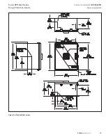
Verify that there is enough space to install the SPD. See Figure 17
for dimensions.
•
Confirm that all tools and equipment needed for the installation
are available.
•
Confirm that the system voltage and wiring configuration is the
same as the SPD you are installing. Check the voltage rating label
on the side of the SPD.
m
WARNING
TURN OFF THE POWER SUPPLY BEFORE WORKING IN ANY ELECTRICAL
CABINET OR ON ANY CIRCUIT BREAKER PANEL. FAILURE TO DO SO
COULD RESULT IN INJURY OR DEATH FROM ELECTRICAL SHOCK
NOTICE
A POOR GROUND, OR GROUNDING/BONDING VIOLATIONS, COULD
PREVENT THE SPD FROM PERFORMING AS SPECIFIED.
DO NOT USE THE SPD TO CARRY OR PASS THROUGH GROUND TO OTHER
DEVICES OR LEADS. DAMAGE TO THE EQUIPMENT MAY RESULT.
•
Check the facility grounding system. All grounding, bonding, and
earthing must meet the NEC, CEC and any other national, state
and local electrical codes.
•
An insulated grounding conductor that is identical in size and
insulation material and thickness to the grounded and ungrounded
circuit supply conductors, except that it is green with or without
one or more yellow stripes, is to be installed as part of the circuit
that supplies the SPD Max Series unit.
•
Refer to Table 250-122 of the NEC to select the appropriate size
of the grounding conductor. This grounding conductor is to be
grounded to earth at the service equipment or other acceptable
building earth ground such as the building frame in the case of a
high steel-frame structure.
•
Any attachment-plug receptacles in the vicinity of the SPD Max
Series unit are to be of a grounding type, and the grounding con-
ductors serving these receptacles are to be connected to earth
ground at the service equipment or other acceptable building
earth ground such as the building frame in the case of a high-rise
steel-frame structure.
•
Pressure terminal or pressure slicing connectors and soldering
lugs used in the installation of the SPD Max Series unit shall be
identified as being suitable for the material of the conductors.
Conductors of dissimilar metals shall not be intermixed in a termi-
nal or splicing connector where physical contact occurs between
dissimilar conductors unless the device is identified for the pur-
pose and conditions of use.
2.2 Installation Locations
Eaton’s SPD Max Series can be installed next to, above, or below
any existing electrical enclosure.
The ideal mounting location for the Eaton SPD Max Series is as
close as possible to the electrical enclosure and should be mounted
in such a way as to minimize the cable length and eliminate any
sharp bends in the wiring conduit.


