4
Instruction Booklet
IB158002EN
Effective October 2018
Eaton SPD Max Series
Surge Protective Device
EATON
www.eaton.com
2.3 Installation Procedures
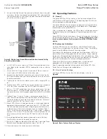
1. Before mounting the SPD Max Series device ensure that the
mounting surface is sufficient to support the weight of the
SPD. See Section 5.0 Specifications for weight. The SPD should
be mounted as close as possible to the electrical cabinet and
as close as possible to the wiring connection point within the
electrical cabinet. This will ensure a minimum wire length and
maximum SPD performance. Preferred entry of the incoming
power is on the hinge side of the enclosure. This location offers
the best VPR ratings. Top and bottom entry is also available. If
the user chooses to wire the entry cable through the top of the
enclosure the internally mounted terminal block for the neutral (if
equipped) and ground connections must be moved to the bottom
of the enclosure. See Section 2.3.1 Installation Procedures for
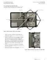
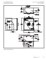
Top Entry. The three possible power entry locations are identified
on the enclosure with a dimple located on the top, bottom and
hinge side of the enclosure housing (see
Figure 16
).
Table 2. Suggested Entry Cable and Conduit Hub Sizes
Power entry into
enclosure
Max. – Min. Entry Cable
AWG
Max. Trade size Hub
Top
1/0 – 10 AWG
1 ½”
Hinge Side
1/0 – 10 AWG
2”
Bottom
1/0 – 10 AWG
1 ½”
2. Layout the four enclosure mounting holes using the enclosure
dimensions provided in
Figure 16
. Drill the appropriate holes per
the product dimensions.
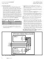
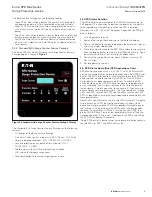
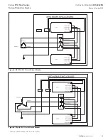
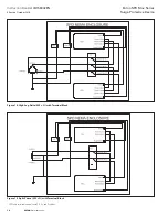
Figure 2. Typical Form C Wiring Connections
3. Determine the correct metal conduit for phase wires using
Table 2
and install onto the SPD enclosure. If using the Form C
contacts route Form C wires through a separate maximum ¾ inch
trade size hub and conduit.*
4. Determine the hole location on the receiving electrical enclosure
and either remove the knock-out provided or drill the appropriate
size hole at that location.
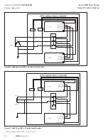
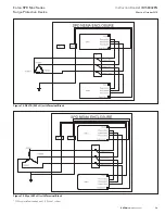
5. Select the correct wiring diagram for the SPD Max you are install-
ing. Refer to the wiring diagrams in
Figures 8-15
6. Determine the wire gauge and length required to make the SPD
phase connections and cut the wires to the appropriate length.
(To maximize SPD performance, wire length should be as short as
possible). Connect the Phase wires through the metal conduit.
otee:
N
Wires should not exceed the allowable bend radius according to NEC
and CEC during installation. Route all Phase, Ground and Neutral (where
applicable) wires through conduit. Route Form C wires (where applicable)
through a separate max. 3/4 inch trade size hub and conduit.*
7. Determine the wire length for the Ground and Neutral (where
applicable) wires and cut these wires as needed. Again, keep
these wires as short as possible to maximize SPD performance
and don’t exceed the bend radius of the wire during installation.
8. Standard with Surge Counter devices also provide wiring for
Form C relay contacts. This connection can be used for remote
monitoring of the SPD. The Form C contacts are rated max 0.46
A, 150 Vac, 1A, 30 Vdc.* Note: when a SPD Max contains two
SPD modules the user can connect their Form C wires to either
SPD1 or SPD2. There is no need to wire to both units as they
are wired together through the SPD Status board and two ribbon
cables. (See Figure 2). Follow all national, state and local electri-
cal codes when making these connections.
*Notee: Utilization of Form C contacts is optional. Connection is
not mandatory for the operation of the SPD.


