6
Instruction Booklet
IB158002EN
Effective October 2018
Eaton SPD Max Series
Surge Protective Device
EATON
www.eaton.com
3.0 Operating Features
3.1 General
The Eaton SPD Max Series comes in two feature packages: Basic,
and Standard with Surge Counter. The operating specifics of each
feature package are described below.
The Eaton SPD Max Series requires no operator involvement other
than to monitor the display panel or the audible alarm (if equipped)
to determine status of the SPD(s).
After system power is applied, the SPD automatically begins protect-
ing downstream electrical equipment from voltage transients and
surges.
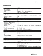
Some SPD Max Series units have a Form C relay contact that allows
for the remote indication of SPD status.
Wiring of the Form C con-
tacts is not mandatory for the operation of the SPD Max Series
device.
3.2 Displays and Indicators
All Eaton SPD Max Series units (Basic, and Standard with Surge
Counter) use a display panel to indicate system status. The display
panel is slightly different for each feature package.
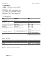
Each display has both green and red light emitting diodes (LEDs) to
indicate the status of the protection on each phase. Green indicates
the phase is fully protected. Red indicates a loss of protection. Wye,
Split Phase and High-Leg Delta units have an additional set of green/
red LEDs to indicate status of Neutral/Ground protection.
When the LED(s) turn red, an audible alarm will also sound if
equipped with a Standard with Surge Counter display.
Specific operating conditions displayed for each Eaton SPD Max
Series Feature Package is described below.
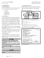
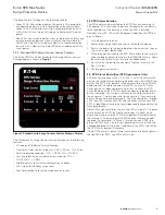
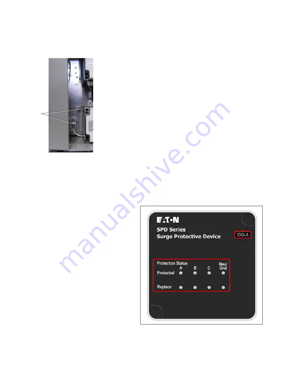
3.2.1 Basic Feature Package
The Eaton SPD Max Series Basic Feature display is shown in
Figure 6
.
Figure 6. Basic Feature Package Display
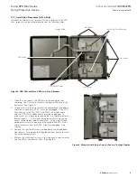
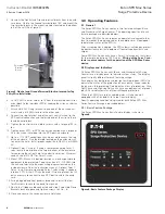
5. Unscrew the Neutral and Ground terminal blocks from the enclo-
sure base. Rotate the Ground terminal block 180o and mount the
two terminal blocks in the mounting holes located on the bottom
left of the unit. (See Figure 5)
Figure 5. Neutral and Ground Terminal Block re-located for Top
Entry Wire Installation
6. Cut #10 AWG neutral wire(s) to fit from the relocated neutral ter-
minal block to the individual SPD(s) keeping the wires as short as
possible.
7. Attach a #10 AWG ring terminal to one end of the new neutral
wire(s) and a #10 AWG ferrule to the other end.
8. Connect the ring terminal end of the new neutral wire(s) to the
SPD neutral connection and the ferrule end of the wire to the re-
located neutral block.
9. Tighten the neutral terminal block screws with a torque of 50 in-
lbs.
10. Tighten either SPD1 or SPD2 neutral connection with a torque of
36 in-lbs, which is molded into the SPD plastic enclosure.
11. Up to a 1 1/2 NPT conduit punch can be used to access the top
of the enclosure. Use the dimple located on the enclosure wall
to center the hole. Install proper conduit hub, NEMA 4 or NEMA
4X.
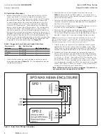
12. Optional Form C wiring - If using a remote monitoring Form C
relay, locate the dimples on the top or bottom of the enclosure
for centering the cut-out hole for conduit installation. Maximum
conduit size of 3/4 NPT for Form C wires.
13. Mount SPD Max unit in desired location as close as possible to
equipment to be protected. Feed wire sizes #10 - 1/0 AWG into
the unit and terminate them per wiring diagram located on the
inside enclosure lid or the instruction manual. Optional Form C
Relay - Install remote monitoring Form C relay wiring, if needed,
into one SPD. Either SPD can be used if two are present, but it’s
only necessary to connect to one SPD device within the enclo-
sure.
14. Swing hinged dead front panels closed and re-install the four
Torx® screws to secure the dead front panels.
15. Re-attach all ribbon cable connectors and slide Cable Hold Down
Brackets back into place and tighten screws to 5 Lb - In.
16. Close and secure the seven enclosure lid latches.
Re-located
Terminal
Blocks


