7
Instruction Booklet
IB158002EN
Effective October 2018
Eaton SPD Max Series
Surge Protective Device
EATON
www.eaton.com
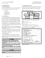
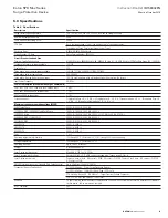
The Basic Feature Package has the following features:
•
Green LEDs: Illumination indicates the phase is fully protected,
and operating normally, with all protection active and available.
Green LEDs also indicate Neutral to Ground protection on units
with a Neutral wire. Green LEDs do not indicate on/off status of
power.
•
Red LEDs: Illumination indicates a loss of protection, and that one
or more protective devices are now inactive and unavailable for
that Phase. Red LEDs also indicate Neutral to Ground protection
on units with a Neutral wire. Red LEDs do not indicate on/off sta-
tus of power.
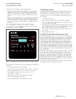
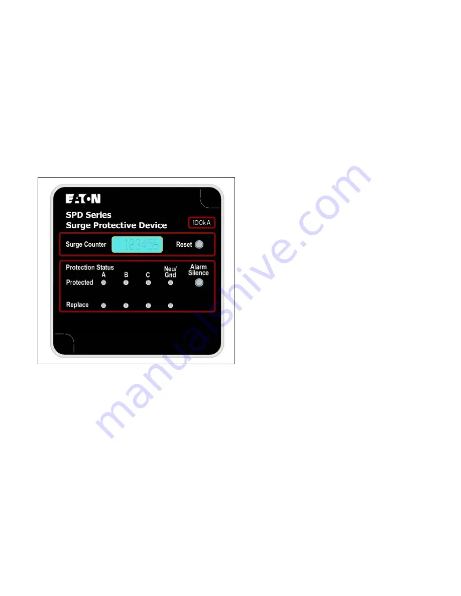
3.2.2 Standard With Surge Counter Feature Package
The Eaton SPD Max Series Standard with Surge Counter Feature
Package display is shown in
Figure 7
.
Figure 7. Standard with Surge Counter Feature Package Display
The Standard With Surge Counter Feature Package has the following
features:
•
All features of the Basic Feature Package.
•
One Form C relay contact rated max 0.46 A, 150 Vac, 1A, 30 Vdc.
•
Normal operating conditions. N.O. = OPEN. N.C = CLOSED.
•
Loss of protection on any phase or loss of power. N.O. =
CLOSED. N.C. = OPEN.
•
Audible alarm with Alarm Silence(Reset) push button.
•
LCD screen that displays surge count.
•
Reset pushbutton to reset the surge counter to zero.
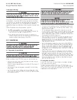
3.3 SPD Display Rotation
The SPD display can be rotated on the SPD Max enclosure, up to
360 degrees. This allows you to position the display for the best vis-
ibility regardless of the position in which the SPD is installed.
Rotations are at 90, 180, and 270 degrees. Reposition the SPD dis-
play as follows:
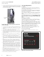
1. Turn off power to the unit.
2. Remove the two phillips head screws that hold the display.
3. Rotate the display to the desired position. Be careful not to over-
stress the display ribbon cable.
4. Place the display back onto the SPD Max enclosure and carefully
align the display gasket to maintain the NEMA4/4X rating. Again,
be careful not to overstress or crimp the ribbon cable.
5. Re-install the two phillips head screws. Tighten screws to 1.35
Nm (12 in-lbs).
6. Restore power to the unit.
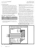
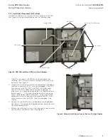
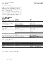
3.4 SPD Status Board (Dual SPD Applications Only)
SPD Max Series devices with a S, U, W or Y suffix, SPMxxxxxxxxY,
contain two internally mounted surge devices and a Dual SPD Status
Board. The SPD Status board is internally mounted in the SPD Max
enclosure and is used to indicate which SPD in a Dual SPD Max
Series device has been compromised or lost. To check the SPD
Status Board open the SPD Max Series enclosure lid by loosening,
but not removing, the 7 screws that secure the lid to the base of
the enclosure. Carefully open the lid and secure it, if necessary, to
ensure it does not close prematurely. The Status board has two red
LEDs; one LED will monitor SPD1 and the other will monitor SPD2.
SPD1 is identified as having the (gray) ribbon cable connected to the
front panel display.
Absent of any phase failures the two red LEDs will be off. If a phase
failure occurs on a SPD, the front panel display will show which
phase had a failure, and the SPD Status board will illuminate one of
the two red LEDs indicating which SPD had the failure and needs
replaced. For example: if a Phase C failure occurs on SPD2, the
green LED for Phase C on the front panel display turns off and the
corresponding red LED turns on. Additionally, the SPD2 red LED on
the SPD Status board will illuminate.
If both SPDs exhibit a phase failure (same phase or different phases)
the red LEDs for SPD1 and SPD2 will turn on.


