background image

9

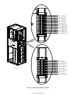
System Parallel Module

Eaton 1+1 120kVA SPM

The utility to SPM

L1

70

1-M16-Bolt-Mounting

210(23.71)

M16 Hex

L2

70

1-M16-Bolt-Mounting

210(23.71)

M16 Hex

L3

70

1-M16-Bolt-Mounting

210(23.71)

M16 Hex

N

70

1-M16-Bolt-Mounting

210(23.71)

M16 Hex

The SPM to Load

L1

70

1-M16-Bolt-Mounting

210(23.71)

M16 Hex

L2

70

1-M16-Bolt-Mounting

210(23.71)

M16 Hex

L3

70

1-M16-Bolt-Mounting

210(23.71)

M16 Hex

N

70

1-M16-Bolt-Mounting

210(23.71)

M16 Hex

The UPS to SPM MOB

L1

70

1-M16-Bolt-Mounting

210(23.71)

M16 Hex

L2

70

1-M16-Bolt-Mounting

210(23.71)

M16 Hex

L3

70

1-M16-Bolt-Mounting

210(23.71)

M16 Hex

N

70

1-M16-Bolt-Mounting

210(23.71)

M16 Hex


Ground

70

1-M10-Bolt-Mounting

45(5.1)

M10 Hex

Eaton 2+1 120kVA SPM

The utility to SPM

L1

240

1-M16-Bolt-Mounting

210(23.71)

M16 Hex

L2

240

1-M16-Bolt-Mounting

210(23.71)

M16 Hex

L3

240

1-M16-Bolt-Mounting

210(23.71)

M16 Hex

N

240

1-M16-Bolt-Mounting

210(23.71)

M16 Hex

The SPM to Load

L1

240

1-M16-Bolt-Mounting

210(23.71)

M16 Hex

L2

240

1-M16-Bolt-Mounting

210(23.71)

M16 Hex

L3

240

1-M16-Bolt-Mounting

210(23.71)

M16 Hex

N

240

1-M16-Bolt-Mounting

210(23.71)

M16 Hex

The UPS to SPM MOB

L1

70

1-M16-Bolt-Mounting

210(23.71)

M16 Hex

L2

70

1-M16-Bolt-Mounting

210(23.71)

M16 Hex

L3

70

1-M16-Bolt-Mounting

210(23.71)

M16 Hex

N

70

1-M16-Bolt-Mounting

210(23.71)

M16 Hex


Ground

240

1-M10-Bolt-Mounting

45(5.1)

M10 Hex

Eaton 3+1 120kVA SPM

The utility to SPM

L1

500

1-M16-Bolt-Mounting

210(23.71)

M16 Hex

L2

500

1-M16-Bolt-Mounting

210(23.71)

M16 Hex

L3

500

1-M16-Bolt-Mounting

210(23.71)

M16 Hex

N

500

1-M16-Bolt-Mounting

210(23.71)

M16 Hex

The SPM to Load

L1

500

1-M16-Bolt-Mounting

210(23.71)

M16 Hex

L2

500

1-M16-Bolt-Mounting

210(23.71)

M16 Hex

L3

500

1-M16-Bolt-Mounting

210(23.71)

M16 Hex

N

500

1-M16-Bolt-Mounting

210(23.71)

M16 Hex

The UPS to SPM MOB

L1

70

1-M16-Bolt-Mounting

210(23.71)

M16 Hex

L2

70

1-M16-Bolt-Mounting

210(23.71)

M16 Hex

L3

70

1-M16-Bolt-Mounting

210(23.71)

M16 Hex

N

70

1-M16-Bolt-Mounting

210(23.71)

M16 Hex


Ground

500

1-M10-Bolt-Mounting

45(5.1)

M10 Hex

model

Cable

Terminal

minimum 

conductor 

size

(mm

2

)

number and size of Pressure 

termination

Tightening 

Torque nm(lb 

in)

screw size and 

type

Table 3-3 . External Power Wiring requirements for 93E and 93Pm

Summary of Contents for SPM 120

Page 1: ...System Parallel Module Installation and Operation Manual Eaton UPS Accessories...

Page 2: ......

Page 3: ...f the information contained in this manual but no liability can be accepted for any errors or omission The right to make design modifications is reserved IMPORTANT SAFETY INSTRUCTIONS SAVE THESE INSTR...

Page 4: ...er Location 12 4 Installation 13 4 1 Preliminary Installation Information 13 4 2 Unloading the SPM Cabinet from the Pallet 13 4 3 External Power Cables Connecting 15 4 4 External Signaling Cables Conn...

Page 5: ...BottomViews 7 Figure 3 3 SPM Cabinet as Shipped on Pallet wood container removed 12 Figure 3 4 Breaker Location 12 Figure 4 1 Removing the Front Shipping Bracket 14 Figure 4 2 Attaching the Ramp to t...

Page 6: ...List of Tables Table 3 1 SPM CabinetWeights 6 Table 3 2 SPM Cabinet Clearances 6 Table 3 3 External PowerWiring Requirements for EBCB 9...

Page 7: ...SPM Startup and operational checks must be performed by an authorized Eaton Customer Service Engineer or the warranty terms specified become void This service is offered as part of the sales contract...

Page 8: ...PS systems in a 2 1 system 120kVA to allow 2x 120kVA UPS systems in a 1 1 system 600kVA to allow 4 x 200kVA UPS systems in a 3 1 system 400kVA to allow 3x 200kVA UPS systems in a 2 1 system 200kVA to...

Page 9: ...g reuse or hazardous waste centre This symbol indicates that you should not discard waste electrical or electronic equipment WEEE in the trash For proper disposal contact your local recycling reuse or...

Page 10: ...Accessory or UPS operation by any action that includes removal of the earth ground connection with loads attached Ensure all power is disconnected before performing installation or service ELECTRIC EN...

Page 11: ...al checks for parallel systems or installations with accessory cabinets must be performed by an authorized Eaton Customer Service Engineer or the warranty terms may become void This service is offered...

Page 12: ...s No special rear clearances required for the SPM other clearances around the SPM cabinet can follow the UPS The basic environmental requirements for operation of the UPS and Accessories are AmbientTe...

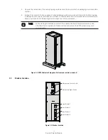
Page 13: ...Right and Rear Views Dimensions are in millimetres inches FrontView RightView RearView TopView BottomView Dimensions are in millimetres inches Figure 3 2 SPM Cabinet Dimensions Top and Bottom Views Ca...

Page 14: ...h for UPS cabinet conduit and terminal specifications and locations The term line up and match refers to accessory cabinets that are physically located adjacent to the UPS The term standalone refers t...

Page 15: ...M16 Hex L3 240 1 M16 Bolt Mounting 210 23 71 M16 Hex N 240 1 M16 Bolt Mounting 210 23 71 M16 Hex The UPS to SPM MOB L1 70 1 M16 Bolt Mounting 210 23 71 M16 Hex L2 70 1 M16 Bolt Mounting 210 23 71 M16...

Page 16: ...Bolt Mounting 210 23 71 M16 Hex L3 630 1 M16 Bolt Mounting 210 23 71 M16 Hex N 630 1 M16 Bolt Mounting 210 23 71 M16 Hex The UPS to SPM MOB L1 150 1 M16 Bolt Mounting 210 23 71 M16 Hex L2 150 1 M16 B...

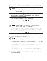
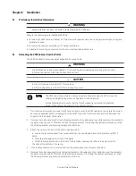
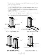
Page 17: ...ackets and ramp extension packed at the top of the cabinet a Straighten the tabs securing the top panel of the wooden container to the side panels of the container b Remove the top panel and retain fo...

Page 18: ...ner 6 Inspect the contents for any evidence of physical damage and compare each item with the Bill of Lading If damage has occurred or shortages are evident contact an Eaton service representative imm...

Page 19: ...ace the ramp against the front of the pallet c Attach the ramp extension to the front of the ramp by inserting the tabs on the extension into the slots at the bottom of the ramp 4 If the leveling feet...

Page 20: ...vel 10 If permanently mounting the system proceed to Step 11 11 Using the retained hardware reinstall the shipping brackets removed in Step 2 and Step 5 to the front and rear of the UPS cabinet with t...

Page 21: ...n and terminal locations See paragraph 3 2 2 Table 3 3 for wiring and termination requirements The utility source must be the same as the UPS bypass input 5 Route and Connect the power cables L1 L2 L3...

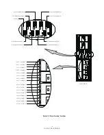
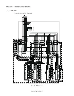
Page 22: ...To Utility Connections L2 To Utility Connections N To Utility Connections L3 To Utility Connections L1 To UPS1 Output N To UPS2 Output N To UPS3 Output N To UPS4 Output N To UPS1 Output L1 To UPS2 Out...

Page 23: ...N7 To UPS2 Interface CN7 To UPS2 Interface CN7 To UPS1 Interface CN7 To UPS1 Interface CN7 To UPS4 Building Alarm2 To UPS4 Building Alarm2 To UPS3 Building Alarm2 To UPS3 Building Alarm2 To UPS2 Build...

Page 24: ...r must verify the operation of the UPS system and commission it to support the critical load The service representative cannot perform any installation tasks other than verifying software and operatin...

Page 25: ...19 System Parallel Module Notes...

Page 26: ...Card Slot 2 ALARM INPUTS Input1 Communications Panel 1 2 Input2 3 4 Input3 5 6 EPO NC 1 2 NO 3 4 Pull Chain 1 2 PARALLEL SIGNALS RJ45 RJ45 CAN IN CAN OUT Card Slot 1 Card Slot 2 ALARM INPUTS Input1 Co...

Page 27: ...DAILY Maintenance 6 2 2 PERIODIC Maintenance 6 2 3 ANNUAL Maintenance 6 2 4 BATTERY Maintenance Perform the following steps daily 1 Check the area surrounding the UPS system Ensure the area is not clu...

Page 28: ...MBS Amps 705 1173 Max current of MIS Amps 654 1086 Max current of MOB Amps 218 362 Operating Temperature 5 C 40 C Storage Temperature 25 C to 55 C Transit Temperature 25 C to 60 C Humidity 5 to 95 ma...

Page 29: ......

Page 30: ......

Page 31: ......

Page 32: ...614 01728 00...

Reviews: