Operation through
MODBUS RTU
34
07/09 MN03407002Z-EN
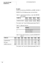
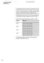
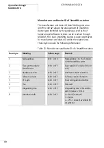
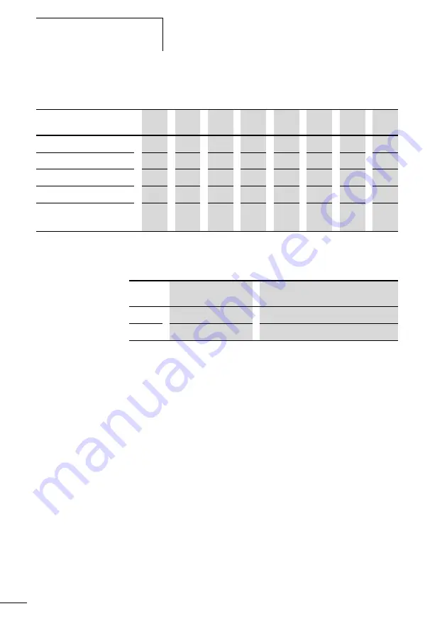
Table 14: Status data (read data, as seen from MODBUS RTU
master)
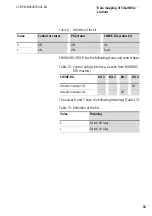
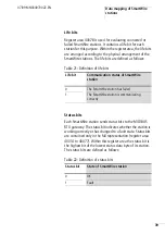
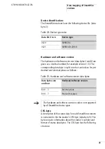
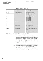
The values 0 and 1 have the following meanings (Table 15):
Table 15: Definition of the bit
The display format for status and control data depends on
the selected register area.
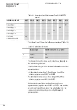
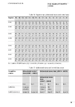
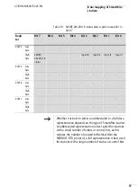
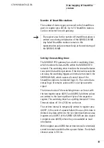
For the status data you can select two different abbreviated
representations:
• Abbreviated status data 1: Two bits per SmartWire
station, register area 40007 to 40008
• Abbreviated status data 2: Four bits per SmartWire
station, register area 40010 to 40013
Abbreviated control data can be shown only in one
representation (register area 40001 to 40002) and contain
two bits per SmartWire station. The table below lists the
status and control data shown in each abbreviated
representation.
SWIRE-4DI-2DO-R
Bit 7
Bit 6
Bit 5
Bit 4
Bit 3
Bit 2
Bit 1
Bit 0
Status input I1
0/1
Status input I2
0/1
Status input I3
0/1
Status input I4
0/1
Status bit
SWIRE-4DI-2DO-R
0/1
Status input
SWIRE-4DI-2DO-R status bit
0
Input 0
OK
1
Input 1
Fault
Summary of Contents for SWIRE-GW-MB
Page 14: ...10 07 09 MN03407002Z EN ...
Page 26: ...22 07 09 MN03407002Z EN ...
Page 30: ...26 07 09 MN03407002Z EN ...
Page 58: ...54 07 09 MN03407002Z EN ...
Page 63: ...Dimensions 59 07 09 MN03407002Z EN Dimensions M4 7 5 35 5 7 5 90 102 110 105 109 4 5 ...
Page 64: ...60 07 09 MN03407002Z EN ...


