15
Instruction Manual IM02602008E - Rev. D
Transformer Temperature Controllers
IM02602008E - Rev. D May 2019 www.eaton.com
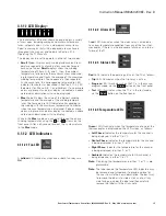
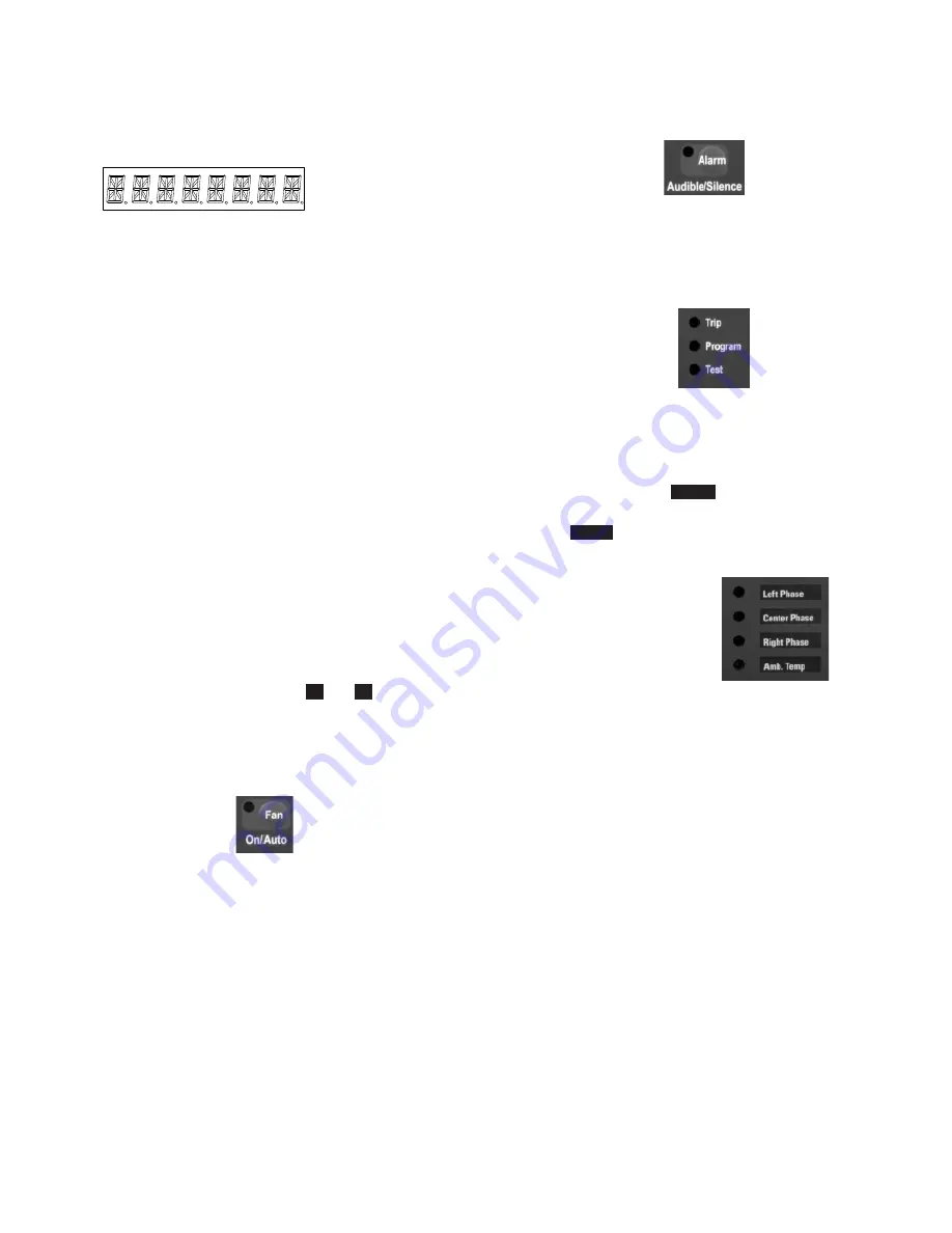
4.1.1.1 LED Display:
The 8-character LED panel, shown above, displays a variety
of messages, including average and maximum tempera-
tures, setpoint values, status, and program menu items.
Specific messages that will be displayed are mentioned
throughout this manual, and notably in Section 4.1.2,
Operating the TC Manually.
The display can be set to operate in either of two modes:
•
Scroll
Mode: Displays each winding (and ambient) tem-
perature sequentially, allowing a few seconds to read
each value. Typical
Scroll
displays show the winding
temperature of Phase A, B, and C, then, the ambient
temperature, followed by the maximum measured wind-
ing temperature, and finally the average of the measured
winding temperatures. The sequence is then repeated.
At the same time, the corresponding temperature LED
indicator illuminates (as described in Section 4.1.1.2, LED
Indicators), for Phase A. B, C and Ambient. If one or more
alarms are present and alarm display is enabled, an abbre-
viated alarm description will also be displayed.
•
Max
Mode: Displays the value of the highest winding
temperature and the average of the winding tempera-
tures. The Temperature LED Indicator corresponding to
the winding with the maximum temperature illuminates
when the max temperature is displayed. If one or more
alarms are present and alarm display is enabled, an abbre-
viated alarm description will also display.
While in the
Max
mode, you can scroll through the phase
winding temperatures using the
and
arrows on the
front panel. After a 60 second time-out, the system returns
to the
Max
mode.
4.1.1.2 LED Indicators
4.1.1.2.1 Fan LED
A
yellow
LED Illuminates when one or both fan relays are
On.
4.1.1.2.2 Alarm LED
A
red
LED illuminates when the alarm relay is active due
to an over-temperature condition from any of the four ther-
mocouples, if there is a thermocouple failure, or an internal
failure of the TC.
4.1.1.2.3 Status LEDs
Red
LEDs Indicate the operating status of the TC as follows:
•
Trip
LED:
Illuminates when the trip relay is active.
•
Program
LED: Illuminates when the TC is in the manual
program mode, via the
Prog
button on the front panel.
•
Test
LED: Illuminates when the TC is in the test mode,
via the
Test
button on the front panel.
4.1.1.2.4 Temperature LEDs
Green
LEDs Illuminate when the temperature of one of the
thermocouples is displayed on the LED screen, as follows:
•
Left Phasee:
Indicates the temperature for this channel is
being displayed, in either °C or °F.
•
Center Phasee:
Indicates the temperature for this channel
is being displayed, in either °C or °F.
•
Right Phasee:
Indicates the temperature for this channel
is being displayed, in either °C or °F.
•
Ambiente:
Indicates the temperature for this channel is
being displayed, in either °C or °F.
otee:
N
Displaying the temperatures in either °C or °F is pro-
grammable.
otee:
N
The label beside the Temperature LED Indicators may
be removed and turned over to provide a place for
the user to write their own description. The best way
to remove the label is to slide a sticky note, sticky
side facing up, under the label and then carefully
remove the label with the sticky note.


