

10
www.eaton.com/wireless
call toll free: 1-800-663-8806
DM-R260-0056A R1
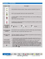
Light Legend
Solid
Slow
Flash
Fast
Flash
Red
Solid
Green
Solid
Red & Green
Alternating
Yellow
Solid
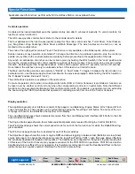
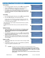
Application-specific functions, performed by RCU and Base Station, are explained below.
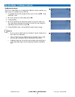
Special Functions
Controls operation
Controls will be locked (disabled) upon the system startup and after 5 minutes of inactivity. To unlock controls, fol-
low the on-screen instruction.
The left 3-axes joystick controls boom. Refer to the controls label for details.
The four paddles and the right 3-axes joystick (except for the knob) control winches: Turret Driver, Turret Passen-
ger, Drag Driver, Drag Passenger, Main Driver and Main Passenger. The winch cables can be fed in or out, as
marked on the controls label.
The knob of the right joystick controls Travel. This function is only available on the Roller option of the system.
Sudden reverse of any operation is prohibited. To change the direction of a particular operation, stop the control (a
paddle or a joystick) in the neutral position momentarily, before proceeding to the opposite side of the axis.
Any winch or combination of winches can be locked in place by holding the Winch switch in the “Lock” position and
moving the corresponding winch control (paddle or joystick) at the same time. The control can be moved in either
direction. Double-toggle (two sequential pushes of the switch upward within 0.5 seconds) will lock all winches.
Once locked, the winches can only be unlocked via the LCD screen on a Control Console.
The Main and the Drag winches can operate in “Rabbit” or “Snail” mode. To toggle in between the two modes on a
particular winch, use the same approach as described in the previous paragraph, while holding the Winch switch in
the “2-Speed” position (instead of “Lock”).
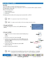
The soft buttons’ operation is explained in the next section.
Concurrent operation of a function on multiple control units (RCU or Control Consoles) is prohibited. A function can
be taken over by another control unit only when the corresponding control is in neutral state. Note that different
functions can be executed simultaneously from multiple control units. For example, one operator can be extending
the boom using the TD3100, while another operator is controlling a winch from one of the Control Consoles.
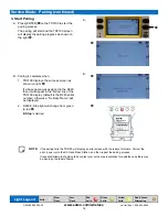
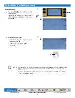
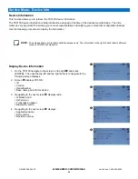
Display operation
The application graphic user interface consists of five pages: Load Balancing, Engine Status, Winch Speed, Winch
Lock and Adjustment. These pages can be cycled through using the “Next Page” soft button. The name of the cur-
rent page is shown in the status bar (the top line) of the display.
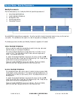
The Load Balancing page shows parameters received from the Load Management Interface (LMI). Refer to the LMI
documentation for details.
The Engine Status page shows a few vehicle operational parameters received from Engine Control Unit (ECU).
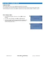
The Winch Speed page shows the current speed mode for each of the four winches for which the Rabbit/Snail tog-
gle is available.
The Winch Lock page shows the Lock status for each of the six winches.
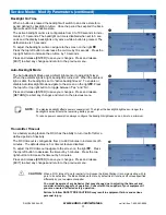
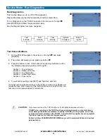
The Adjustment page shows the current engine RPM and allows toggling in between fast (Rabbit) and slow (Snail)
engine idle speed. To change the idle speed, press the top left soft button (“SB1”). Also this page allows offsetting
the sensitivity deadband for paddles and joysticks. The deadband, as configured for the system in general using the
LCD screen of the Control Console, may appear excessive for the TD3100 RCU in particular. TD3100 has a built-in
deadband which is sufficient for any operation. It is therefore recommended to set the Deadband Offset on the Ad-
justment page to a negative number matching the Control Console setting.


