29
www.eaton.com/wireless
call toll free: 1-800-663-8806
DM-R260-0056A R1
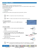
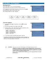
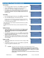
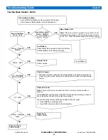
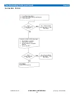
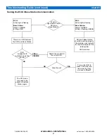
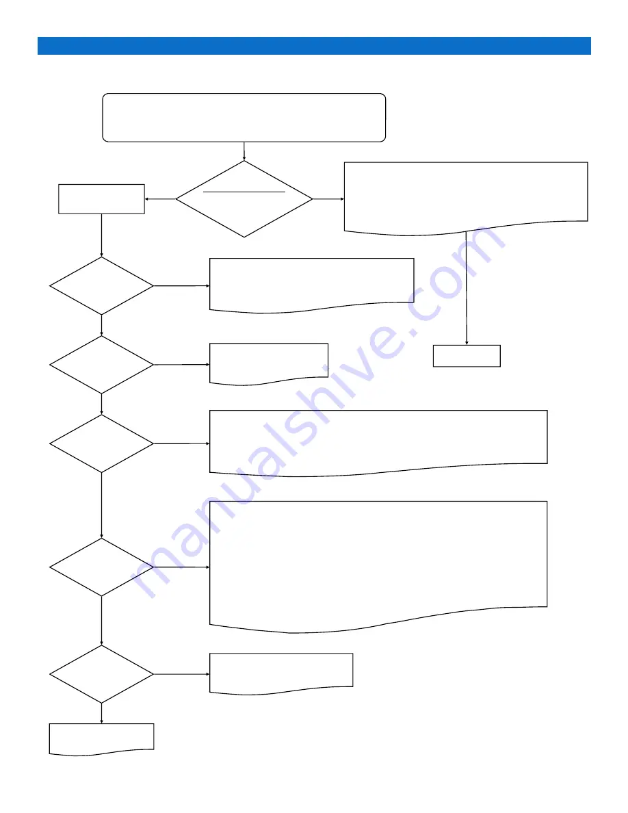
Test the Base Station
-
R260
Start Initial Condition:
Turn off RCU (all lights are off—press the OFF button)
Cycle power to Base Station (turn off and back on)
Error Condition:
Review Lights
Go to
Chart 2
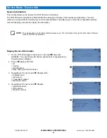
Radio Fault:
Call for service.
Internal Fault:
Call for service.
Short to Supply:
1. Disconnect A & B connectors from Base Station and check all outputs for
power (e.g. bare wires, improper connections) and make the correct adjust-
ments.
Short to Ground:
Note:
This should only occur when the RCU is on and a function button is
pressed.
Go to
Chart 2
to test the RCU. If the RCU is functioning correctly, proceed to
check the status of each of the output connections:
Press each of the function buttons and observe the I/O Light.
turns GREEN, everything is OK.
turns RED, there is a short in that connection.
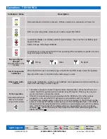
Troubleshooting Guide
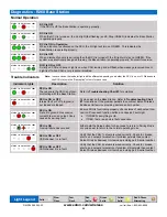
Chart #1
Base Station lights?
Status – GREEN
I/O – OFF/GREEN
E-Stop – RED
Base Station OK:
Note:
If there is a short to ground on an output, it is not
indicated at this stage. To test for short to ground, refer
to the “I/O – RED” troubleshooting at the bottom of page.
Low Battery:
Check that system is wired correctly to battery
and that battery is functioning correctly.
I/O – Alternating
RED & GREEN
Status – Flashing
GREEN
Status – RED
I/O – RED
E-Stop – Flashing
RED
Unknown Fault:
Call for service.
NO
YES
NO
YES
NO
YES
NO
YES
NO
YES
YES
NO


