background image


www.eaton.com/wireless


call toll free: 1-800-663-8806


DM-R260-0056A R1 


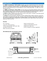
Mounting and Installation 

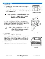
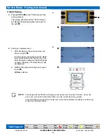
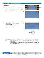
The Base Station can be mounted by fastening two ¼” bolts through the two mounting holes in the unit’s enclosure.  

When mounting, ensure that the Base Station is oriented so that the text is upright and the connector is pointing “down”. 

When selecting a mounting point for the Base Station, it is recommended that the location  



Use a minimal length of wiring to connect it to the control panel




Be in a visible area where it has good exposure to the operator




Be mounted on a surface protected from the weather




Sustains minimal vibration




Has best possible line of sight with the RCU for maximum operational 
range

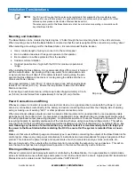
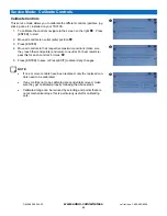
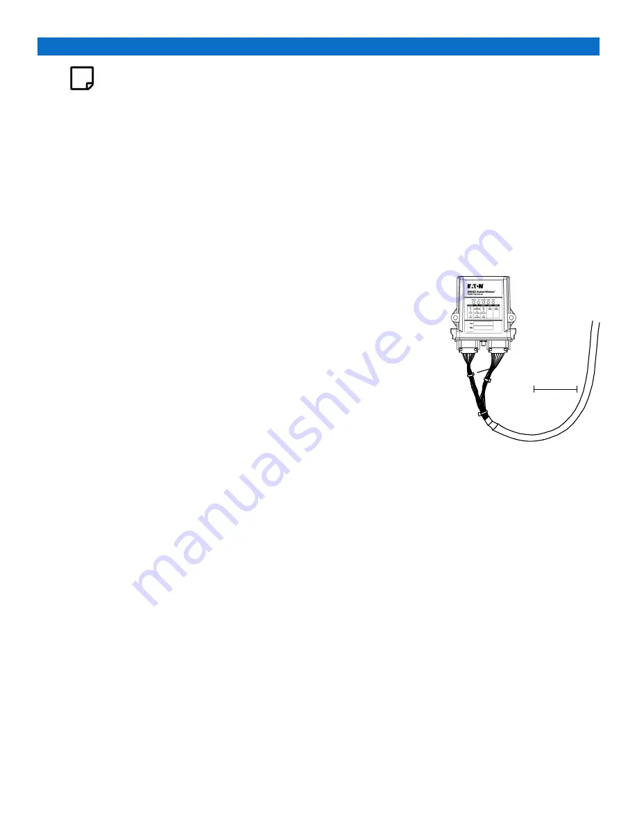
When installing the Base Station, it is recommended that a “Drip Loop” is formed 

with the output cables.  By creating a Drip Loop, water from condensation, rain 

or wet environments, will drip off of the cable instead of running along the wire 

and into the Base Station connections or running along the cables into the ma-

chine’s electronic controls. 

Using approximately 1 foot (30 cm) of cable creates a loop with an approximate 

radius of 3-4 inches (8-10 cm).  Ensure the loop bottom is lower than the Base 

Station connectors. 

If connecting an external antenna, a Drip Loop radius of approximately 2-3 inch-

es (5-8 cm) can be formed from approximately 8 inches (20 cm) of cable. 

Power Connections and Wiring 

Whenever a power connection is made to an electronic device, it is a good practice to make both the Power (+) and 

Ground (-) connections route directly to the battery and avoid connecting the power from the charging side of existing 

wiring or making use of existing "ACC" or other peripheral connection points. 

When proportional voltage outputs are used to operate critical equipment it is good practice to use a separate enable 

signal as part of the control circuit.  In some cases an application can be designed using an independent enable output 

for each proportional output (see wiring diagram).  An alternative solution is to use the “Switches to Power with Link” line 

(see wiring diagram) to explicitly enable each of the functions that are using proportional voltage control.  This will en-

sure that under all fault conditions the equipment will be disabled when the link is disabled (e.g.


by hitting E-Stop).  

As 

well, following any instance of a fault condition (e.g. output shorted) it is recommended practice to fully cycle 

the power to the Base Station before restarting the RCU to ensure that the system is restarted from a known 

state.


Make sure that wire of sufficient gauge and insulator type is used when connecting the outputs of the Base Station to the 

control panel.  Observe any component manufacturer's instructions and recommendations for proper integration of their 

product. This includes the power ratings and requirements of such components as relays, valves, solenoids, etc. 

Be sure to test each of the outputs with a multi-meter prior to connecting the outputs to your end devices.  This will en-

sure that each output has been programmed to operate in the manner required by each end device. 

Filtering and Noise Suppression 

Whenever a solenoid or electromagnetic switch is controlled by the Base Station, it is a good practice to install a diode 

across its terminals to ensure that surges and spikes do not continue back into the circuit.  Appropriate 36V Bi-directional 

Diodes kits can be ordered under the Eaton part number “AKIT-2492-01”. 

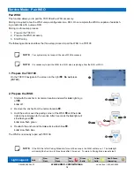
Installation Considerations 


3” - 4 “ 

Drip Loop 

NOTE: 

The FCC and IC require that the antenna be restricted to that supplied by the manufacturer and 

approved for use with this product. An optional 0dB coax wire antenna may be supplied. For other 

antenna options please contact Eaton Wireless Business Unit. 

The antenna(s) used for this Base Station must not be co-located or operating in conjunction with 

any other Base Station. 

Summary of Contents for TD3100

Page 1: ...Miller Industries RaptorSystem Installation Configuration Manual 74 1833 Coast Meridian Road Port Coquitlam BC Canada V3C 6G5 Tel 604 944 9247 Fax 604 944 9267 Toll Free 1 800 663 8806 July 23 2020 DM...

Page 2: ...2 www eaton com wireless call toll free 1 800 663 8806 DM R260 0056A R1...

Page 3: ...ation Mode 21 Service Mode Run Diagnostics 22 Service Mode Device Info 24 Operations TD3100 RCU 25 Operations WSO 26 Operations Charge Cradle 27 Diagnostics R260 Base Station 28 Troubleshooting Guide...

Page 4: ...e to prevent accidental operation of the machine Care KEEP DRY Do not clean the RCU Base Station under high pressure If water or other liquids get inside the RCU bat tery or Base Station compartment i...

Page 5: ...r prohibited Lithium Ion batteries are subject to disposal and recycling regulations that vary by country and region Always check and follow your applicable regulations before disposing of any battery...

Page 6: ...commonly affects licensed radios The R260 Base Station is designed to be powered from a 12VDC or 24VDC system It features 19 solid state high side driver input output controls and a reliable E Stop co...

Page 7: ...part of the control circuit In some cases an application can be designed using an independent enable output for each proportional output see wiring diagram An alternative solution is to use the Switc...

Page 8: ...e programmed splash screen If the RCU is equipped with an optional E Stop the display will take the user through an E Stop check The display will show as a minimum the RF link strength and battery sta...

Page 9: ...tion Momentarily operating any button or control on the RCU including the Power button will restart the timeout monitoring Follow these steps to ensure that there is a radio link between the RCU and B...

Page 10: ...Winch switch in the 2 Speed position instead of Lock The soft buttons operation is explained in the next section Concurrent operation of a function on multiple control units RCU or Control Consoles is...

Page 11: ...The link will be lost un der any of the following circumstances The RCU and Base Station are out of range The RCU is out of batteries The RCU is shut down manually by Power Button The RCU is shut down...

Page 12: ...y splash screen and immediately proceed to next step C Release Button D Release Power Navigation Once you have entered service mode you can move through the option menus by using the top left and righ...

Page 13: ...and Considerations 1 Prepare the TD3100 On the TD3100 navigate to the screen on the right Do not press ENTER at this time NOTE It is necessary to associate the RCU to Base Station when replacing eith...

Page 14: ...E If the R260 is left in Pairing Mode idle for over 30 seconds the R260 will time out The E Stop light will turn red after Pairing Mode times out To return to Pairing Mode repeat step 2 2 Light Legend...

Page 15: ...D3100 will display an error screen with the reason for failure Correct the error power cycle the RCU and Base Station and then repeat the pairing process If repeated attempts at pairing fails contact...

Page 16: ...o 100 in incre ments of 10 The backlight is off at 0 and maximum brightness at 100 The default value is 15 To adjust the backlight brightness navigate to the screen on the right Press the top left but...

Page 17: ...rned off When the ambient light is dark the backlight is set to Active backlight level To enable or disable Auto Backlight Mode navigate to the screen on the right Press the top left or top right butt...

Page 18: ...lacing either the RCU or WSO 2 Prepare the WSO 1 Start with the anchor in its normal location and wait for Link light to go off Link off 2 Remove the anchor from the normal location 3 Hold the anchor...

Page 19: ...display the pairing progress as shown on the right B NOTE If the pairing fails the TD3100 will display an error screen with the reason for failure or the WSO link light with be red Correct the error...

Page 20: ...ve all controls to their respective maximum positions make sure they reach their end points and return to neutral For best results re peat this for each control 2 3 times 5 Press ENTER to save or Pres...

Page 21: ...rs then executing the mode will do nothing Use the following procedures to enter calibration mode and execute any specific application calibration required Run Calibration Mode 1 On the TD3100 navigat...

Page 22: ...utton Position 3 Top Right button Position 4 Bottom Right button Position 5 Power button 4 To quit button testing press EXIT and hold for 2 seconds If a button will not function make sure the button i...

Page 23: ...ean a button or the TD3100 with a soft cloth lightly dampened with water DO NOT clean a button or the TD3100 with any sharp instruments or objects that can cut or damage the button membrane or housing...

Page 24: ...cedures to display the information Display Device Information 1 On the TD3100 navigate to the screen on the right and press ENTER Then use the top left and top right buttons to navigate to the followi...

Page 25: ...n the tether is con nected the RCU is guaranteed not to transmit any RF signals This may be a require ment around some construction zones If the RCU is operating and communicating with the R260 when t...

Page 26: ...ting to establish a link with the RCU it has previously been paired with Pairing Waiting to pair with an RCU WSO updates anchor status and then terminates link with the RCU Link with RCU lost Pairing...

Page 27: ...CAN bus Low CAN HIGH CAN bus High BAT Vehicle battery positive 9 32VDC BAT GND Vehicle battery ground RLY NO RCU Present relay normally open 0 5A max RLY COM RCU Present relay common RLY NC RCU Prese...

Page 28: ...output Likely caused by a wiring fault Ensure RCU is functioning properly check status of each output con nection Press each function button and observe Fault Light If GREEN everything is OK If RED t...

Page 29: ...o Chart 2 to test the RCU If the RCU is functioning correctly proceed to check the status of each of the output connections Press each of the function buttons and observe the I O Light turns GREEN eve...

Page 30: ...ged 3 Turn on the RCU Go to Service Mode Run Diagnostics to test the buttons Complete in order the following steps 1 Check battery orientation 2 Clean battery contacts 3 Check Recharge or Replace batt...

Page 31: ...f the units func tion correctly If not proceed to Chart 1 The RCU code may need to be paired to the Base Station again Troubleshooting Guide continued Chart 3 RCU Active light is flashing Base Station...

Page 32: ...nk light on the Base Station doesn t turn GREEN the Base Station didn t receive all of the information that was sent from the RCU Possible Solutions 1 Try the Downloading steps again 2 If this doesn t...

Page 33: ...Mode Pairing Only proceed if it is not possible to use a magnet to initiate R260 Pairing Mode 1 Opening R260 Case No Magnet Access The case cap is attached to the base by two plastic tabs at opposing...

Page 34: ...R260 E Stop light starts flashing green quickly B NOTE If the R260 is left in Pairing Mode idle for over 30 seconds the R260 will time out The E Stop light will become red after Pairing Mode times ou...

Page 35: ...35 www eaton com wireless call toll free 1 800 663 8806 DM R260 0056A R1 Notes...

Page 36: ...sion Division Wireless Solutions warrants to the original purchaser that the Eaton Wireless products are free from defects in materials and workmanship under normal use and service for a period of ONE...

Reviews: