background image

5

Service

The following instructions describe the
complete rebuilding of your Vickers TE,
TF or TL cylinder.

Refer to Figure 4 exploded view.

                Warning

Before breaking a circuit connection,
make certain that power is off and
system pressure has been released.
Lower all vertical cylinders, discharge
accumulators, and block any load
whose movement could generate
pressure. Plug all removed units and
cap all lines to prevent the entry of dirt
into the system.

Required Tools

Spanner wrench
Adjustable wrench
Soft brass tool
Thin tool (like a metal ruler)
Copper padded vice
Rubber mallet
Torque wrench

Replacing Rod Seals

1. Once the cylinder is removed from

service, fully retract the piston rod
and remove all port connections.
Drain any hydraulic fluid by manually
cycling the cylinder. Large cylinders
can be carefully cycled with air
pressure.

2. The Quick Change rod cartridge

allows rod seal replacement without
disturbing the tie rods. Remove any
burrs from the wrench flat area of the
piston rod. Place the cylinder in a vice,
rod end up if possible. Remove the
rod bearing retainer plate by removing
the retainer screws. The retainer may
be round, square or rectangular.
Round retainers that are recessed into
the head have a pry groove on the
O.D. or two tapped holes to aid
removal.

3. Remove the rod seals on smaller

cylinders by placing your thumb over
the rod end port and giving a quick
pull on the piston rod. Use low
pressure air in the rod end port for
larger cylinders. Leave the bearing
on the rod to catch the seals as they
leave the seal cavity. Note the
position of the male seal adaptor
relative to the bearing and the seals.

Leave the male seal adapter in place
if in the bottom of the seal cavity, to
support the piston rod while
performing the remaining
disassembly.

4. Remove the elastomer rod wiper or

rod scraper retainer from the rod
bearing. Remove the rod scrapers if
applicable.

5. For metallic scrapers, stack the new

scraper rings so that the slots are
staggered. Lightly lubricate the new
wiper or retainer and push it into the
bearing groove with a soft brass tool.

6. Lightly lubricate the new rod seals

and replace, one at a time, by
leading the outside sealing edge with
a soft brass tool as each seal is
inserted in the cavity. Be careful not
to damage the seals when placing
them over the piston rod.

7. Carefully replace the bearing on the

rod. Slide the retainer plate into
position. Replace the retainer
screws, and tighten in a cross
sequence pattern. Torque to values
shown in Table 2 below.

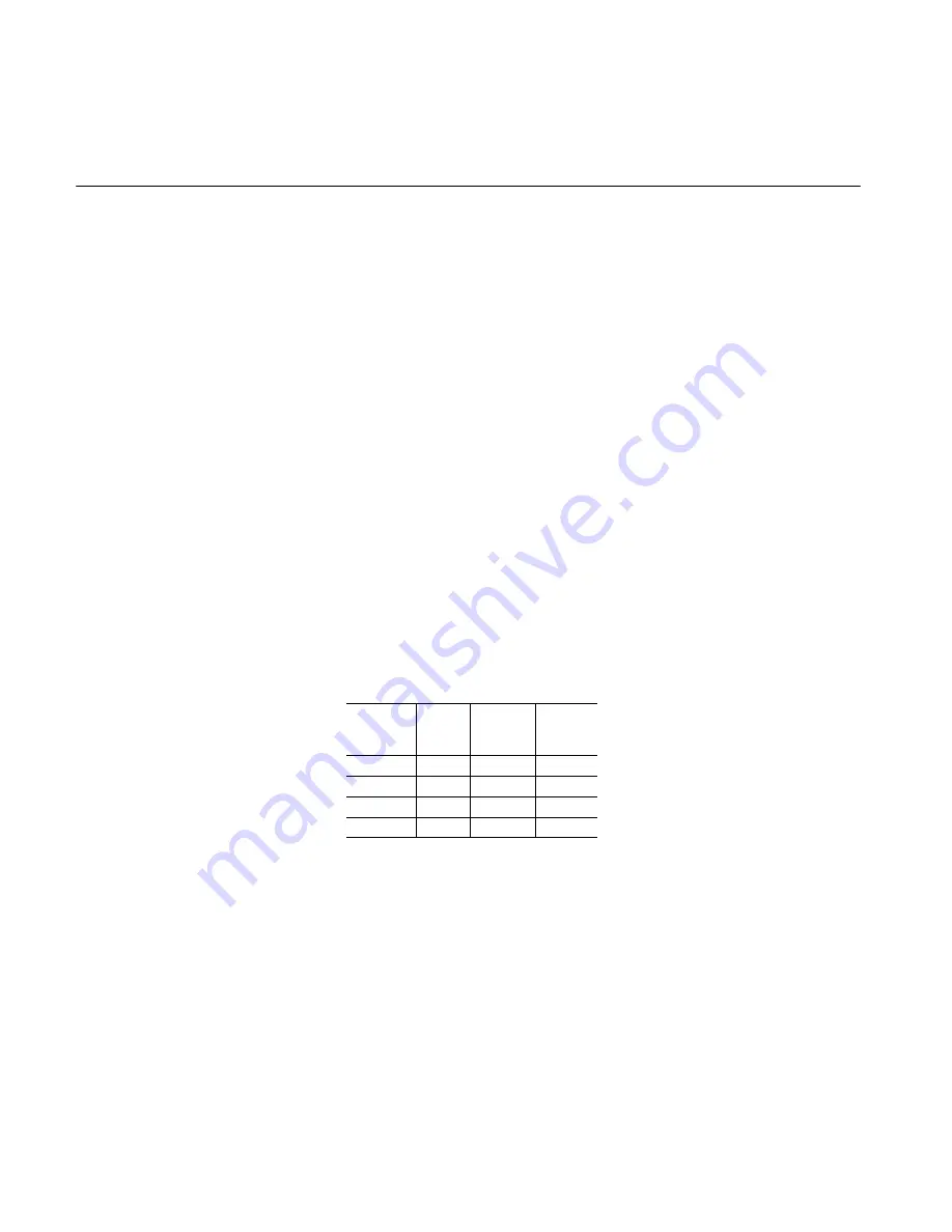
Retainer Screw Torque

Retainer
Screw
Size

Screw
Part #
6893

Screw
Part #
6894

Rec.
Torque
(ft-lbs)

1

/

4

- 28

-1 -2

-1 -2 -3

7

1

/

4

 - 28

-1, -2

-1, -2, -3

7

5

/

16

- 24

-3 -4

-4 -5

12

5

/

16

 - 24

-3, -4

-4, -5

12

3

/

8

- 24

-5

-6 -7

22

3

/

8

 - 24

-5

-6, -7

22

1

/

2

 - 20

-6, -7

-8, -9

50

Table 2.

Complete Rebuild

1. Repeat steps 1, 2, 3, 4 and 5 in

Replacing rod seals section.

2. Remove the tie rod nuts, loosening

in a cross sequence pattern.
Carefully remove the cap or head
from the tie rods and inspect for
damage or signs of contamination.

3. Remove the cylinder body from the

head/cap. Slide the piston rod
assembly out of the cylinder body. It
is not necessary to remove the tie
rods if threaded into a tapped head
or cap for servicing, unless the
tapped head or cap is mechanically
damaged.

4. The piston does not have to be

removed from the rod for normal
piston seal replacement. Cast iron
piston rings may be removed by
inserting a thin tool under the joint
and running it around the
circumference of the piston.

5. Remove the nonmetallic wear band

which simply snaps into the groove
on the piston’s outer diameter, if
applicable.

6. If piston removal from the rod is

required, slide the piston rod
assembly out of the cylinder body.
Clamp the rod securely in a copper
padded vice that will protect the rod
finish. If a locknut holds the piston to
the rod, loosen and remove locknut.

7. If no locknut is present, heat the

piston to approximately 350

_

F with a

torch or in an oven to break the
anaerobic adhesive. Insert a
spanner wrench in the drilled holes
on the piston face and break the seal
by rapping the wrench with a rubber
mallet, rotating the piston in a
counterclockwise direction.

CAUTION

THE PISTON IS HOT!

8. Unscrew the piston and set it aside.

9. Remove the cushion collar from the

rod, if the cylinder is cushioned on
the head end. Let the rod cool before
re-assembly.

10. Snugly secure the rod into the vice.

Replace the cushion collar on the
rod (if required). Thoroughly clean all
metallic surfaces with a
non-petroleum based cleaner and a
wire brush, if necessary.

11. Apply anaerobic adhesive near the

rod shoulder (or collar) on the rod
threads and on the piston I.D.
threads.

NOTE

Be sure to follow the adhesive
manufacturer’s
recommendations regarding
surface preparation, priming
requirements, proper adhesive
for the thread size, and cure time
prior to pressurization. Failure to
do so could result in improper
sealing and retention.

Summary of Contents for TE series

Page 1: ...5075 00 EN 0197 S Series TE TF TL Air Hydraulic Cylinders Installation Service Manual Vickers Cylinders...

Page 2: ...rporated 1997 All Rights Reserved Contents Introduction 1 Cylinder Installation 2 Troubleshooting 3 Service 5 Exploded View 7 Maintenance 7 Replacement Parts 9 How to Order 21 Model Code Cylinder Iden...

Page 3: ...een arranged to cover the vast majority of available options there will be occasions when an option which cannot be coded will be required When such an option has been specified enter an X for the app...

Page 4: ...ssurized relieve all pressure prior to turning the piston rod Piping connections All piping connections should be deburred and the system thoroughly flushed to purge all contaminants prior to connecti...

Page 5: ...c l System pressure in excess of cylinder rating Follow Vickers cylinder catalog design recommendations g seals High pressure developed in cylinder cushion Consult your Vickers Sales Engineer Cyl exte...

Page 6: ...rst blocking the cylinder piston in mid stroke then pressurizing one side of the piston If a rod clevis is available the same check can be done by reversing the clevis on the rod then letting the clev...

Page 7: ...the bearing on the rod Slide the retainer plate into position Replace the retainer screws and tighten in a cross sequence pattern Torque to values shown in Table 2 below Retainer Screw Torque Retainer...

Page 8: ...the piston O D and the rings Carefully insert the piston into the cylinder body 19 Install the body o ring in the head body groove When properly installed the o ring should remain in the head when in...

Page 9: ...damage to the pump can result In suction or return lines loose connections permit air to be drawn into the system resulting in noisy and or erratic operation 2 Clean fluid is the best insurance for lo...

Page 10: ...ydraulic system and careful selection of it should be made with the assistance of a reputable supplier Proper selection of oil assures satisfactory life and operation of system components with particu...

Page 11: ...E53DU0E0 11 Piston locknut 1 364 N A 364 N A 12 Body o ring 2 5145 029 A 5145 029 A 5145 033 A 5145 033 A 13 Cushion seal cap end for cap end cushioned air cylinders only 1 5050 10 5050 10 5050 10 505...

Page 12: ...M 77 6 1 B SM 77 2 B SM 77 4 B SM 77 6 1 B SM 77 8 1 B 6 1 N A 5050 2 Use items 18 19 N A N A 7 1 TE57DA_ _ _ TE57EA_ _ _ TE57EA_ _ _ TE57EA_ _ _ TE57EA_ _ _ 8 1 TE93HD1 TE93CD1 TE93EE1 TE93HD1 TE93LE...

Page 13: ...E53GU0L0 TE53GU0M0 11 Piston locknut 1 664 N A 364 N A 12 Body o ring 2 5145 042 A 5145 042 A 5145 042 A 5145 042 A 13 Cushion seal cap end for cap end cushioned air cylinders only 1 5050 1 5050 1 505...

Page 14: ...4 B SM 77 6 B SM 77 8 B SM 77 9 B SM 77 11 B 6 1 5050 3 N A N A N A N A 7 1 TE57HA_ _ _ TE57HA_ _ _ TE57HA_ _ _ TE57HA_ _ _ TE57HA_ _ _ 8 1 TE93EH1 TE93HH1 TE93LH1 TE93MH1 TE93PH1 9 2 5120 40 5120 40...

Page 15: ...E0 TE53KU0H0 TE53KU0L0 TE53KU0M0 11 Piston locknut 1 664 N A 364 N A 12 Body o ring 2 5145 049 A 5145 049 A 5145 049 A 5145 049 A 13 Cushion seal cap end for cap end cushioned air cylinders only 1 505...

Page 16: ...1 SM 77 11 B SM 77 18 B SM 77 14 B SM 77 6 B SM 77 8 B 6 1 N A N A N A 5050 4 5050 4 7 1 TE57KA_ _ _ TE57KA_ _ _ TE57KA_ _ _ TE57LA_ _ _ TE57LA_ _ _ 8 1 TE93PH1 TE93UH1 TE93VK1 TE93HL1 TE93LL1 9 2 512...

Page 17: ...U0P0 TE53LU0W0 TE53MU0H0 TE53MU0L0 11 Piston locknut 1 N A N A N A N A 12 Body o ring 2 5145 163 A 5145 163 A 5145 167 A 5145 167 A 13 Cushion seal cap end for cap end cushioned air cylinders only 1 5...

Page 18: ...5070 44 5 1 SM 77 18 B SM 77 16 B SM 77 6 B SM 77 8 B SM 77 14 B 6 1 N A N A 5050 4 5050 4 N A 7 1 TE57MA_ _ _ TE57MA_ _ _ TE57NA_ _ _ TE57NA_ _ _ TE57NA_ _ _ 8 1 S 693 300 TE93ZN1 TE93HL1 TE93LL1 S...

Page 19: ...ton 1 TE53NU0L0 S 1053 U S 1053 U S 1053 U 350 11 Piston locknut 1 N A N A N A N A 12 Body o ring 2 5145 171 A 5145 274 A 5145 274 A 5145 274 A 13 Cushion seal cap end for cap end cushioned air cylind...

Page 20: ...070 49 5070 55 5 1 SM 77 19 B SM 77 9 B SM 77 11 B SM 77 22 B SM 77 19 B 6 1 N A N A 5050 4 5050 4 N A 7 1 TE57RA_ _ _ TE57SA_ _ _ TE57SA_ _ _ TE57SA_ _ _ TE57SA_ _ _ 8 1 S 893 550 TE93LR1 TE93PL1 TE9...

Page 21: ...300 S 1453 U 400 S 1453 U 550 11 Piston locknut 1 N A N A N A N A 12 Body o ring 2 5145 280 A 5145 280 A 5145 280 A 5145 280 A 13 Cushion seal cap end for cap end cushioned air cylinders only 1 5050...

Page 22: ...20 Exploded view 1 10 13 12 11 23 26 25 2 3 5 4 7 8 Figure 5 12 20 21 9 6 24 22 18 19 17 15 14 15 16...

Page 23: ...ur local Vickers sales engineer to identify and service your Vickers cylinder Custom Cylinders New Cylinders Although the model code has been arranged to cover the vast majority of available options t...

Page 24: ...2 Cap Extended Tie Rod 22 MX3 Head Extended Tie Rod 23 MX1 Both Ends Extended Tie Rod 25 Double Rod Side Lug Code Other mounting styles 24 No Mount 26 Double Rod Tapped 28 Double Rod Keyed Side Lug 29...

Page 25: ...D 1 E F G H 1 3 8 J K L M 1 3 4 N P R S 2 1 2 1 A B C D 1 3 8 E F G H 1 3 4 J K L M 2 N P R S 3 1 4 1 A B C D 1 3 8 E F G H 1 3 4 J K L M 2 N P R S 2 1 2 T U V W 4 1 A B C D 1 3 8 E F G H 1 3 4 J K L...

Page 26: ...1 C 2 01 D 3 01 E 4 01 F 1 1 01 G 2 2 01 H 3 3 01 J 4 4 01 K 1 01 L 2 01 M 3 01 N 4 01 P 1 PS200 R 2 PS200 S 3 PS200 T 4 PS200 U 1 1 PS200 V 2 2 PS200 W 3 3 PS200 Y 4 4 PS200 1 1 PS200 2 2 PS200 3 3 P...

Page 27: ...Seal Kits A complete Series 63 seal kit contains the following items 3 Rod seals 2 Body o rings 2 Piston seals U cup 2 Cushion screw o rings Series TE TF TL Cylinder Repair Kits Standard Nitrile Elast...

Page 28: ...0 ISO 9001 CERTIFICATED FIRM DET NORSKE VERITAS INDUSTRY BV THE NETHERLANDS ACCREDITED BY THE DUTCH COUNCIL FOR CERTIFICATION Reg No 24 Quality System Certified Products in this catalog are manufactur...

Reviews: