background image

Eaton Tripp Lite Series SmartPro User Guide 614-40194—Rev 03

5

22..33

R

Reeaarr ppaanneell

1

2

3

4

5

6

7

8

9

10

11

12

4

2

4

12

1

3

5

8

10

11

4

3

9

6

7

3

1

3

5

8

10

11

4

3

2

4

12

9

6

7

3

2

4

12

1

3

5

8

4

3

9

6

7

3

1

3

5

8

4

3

2

4

12

9

6

7

3

10

11

12

11

10

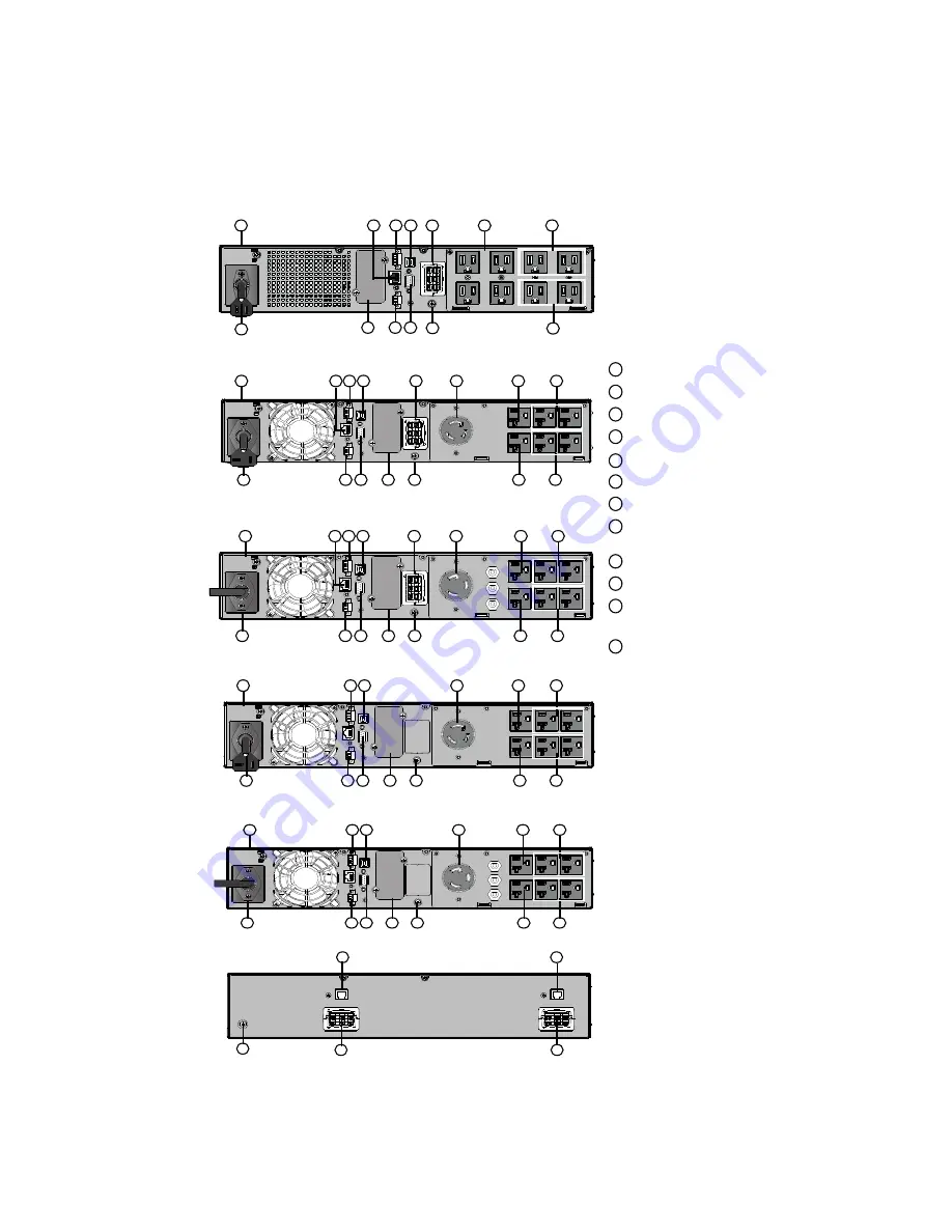
SMART750RMXL2U / SMART750RMXL2UN / SMART1000RMXL2U /

SMART1000RMX2UN / SMART1500RMXL2U / SMART1500RMXLN

SMART2200RMXL2U / SMART2200RMXLN

SMART3000RMXL2U / SMART3000RMXLN

BP48VRM2U / BP72VRM2U

SMART2200RM2U / SMART2200RM2UN

SMART3000RM2U / SMART3000RM2UN

1
2
3
4

5
6

7
8

9

10

11

12

UPS

Input AC power source
Primary group (critical equipment)
Outlet group (programmable outlets)
USB communication ports
RS232 communication port
Relay output contact
Connector for ROO (Remote On/Off) control and 

RPO ( Remote Power Off)
Slot for optional communication card
Connector for additional battery module
Connector for automatic recognition of an additional 

battery module
Ground screw

Rear panel

Summary of Contents for Tripp Lite Series SmartPro Series

Page 1: ...MART3000RM2U SMART3000RM2UN SMART750RMXL2U SMART750RMXL2UN SMART1000RMXL2U SMART1000RMX2UN SMART1500RMXL2U SMART1500RMXLN SMART2200RMXL2U SMART2200RMXLN SMART3000RMXL2U SMART3000RMXLN BP48VRM2U BP72VR...

Page 2: ...an radiate radio frequency energy and if not installed and used in accordance with the instruction manual may cause harmful interference to radio communications Operation of this equipment in a reside...

Page 3: ...range of temperature Operating range of humidity The UPS and their batteries must be kept in a ventilated place S Sa af fe et ty y o of f P Pe er rs so on ns s The system has its own power source the...

Page 4: ...ly damp environment Never let a foreign body penetrate inside the system Never block the ventilation grates of the system Never expose the system to direct sunlight or source of heat If the system mus...

Page 5: ...n with a HotSwap MBP Maintenance ByPass optional module 13 3 7 1 UPS Start Up with the HotSwap MBP Module 14 3 7 2 HotSwap MBP module test 14 3 8 HotSwap MBP module test 14 4 4 I In nt te er rf fa ac...

Page 6: ...7 3 Silencing the Alarm 31 7 4 Service and Support 31 8 8 S Sp pe ec ciif fiic ca at tiio on ns s 3 33 3 8 1 UPS Model List 33 8 2 Extended Battery Module Model List 33 8 3 Weights and Dimensions 33...

Page 7: ...C 03 Low density polyethylene LDPE 04 Polypropylene PP 05 Polystyrene PS 06 Follow all local regulations for the disposal of packing materials E En nd d o of f lliif fe e Eaton Tripp Lite Series will...

Page 8: ...n off ROO and remote power off RPO Backed by worldwide agency approvals 1 1 3 3 S Sp pe ec ciia all P Pr re ec ca au ut tiio on ns s The unit is heavy wear safety shoes and use vacuum lifter preferent...

Page 9: ...50RMXL2UN 44 5 20 2 17 6x17 2x3 4 448x438x85 5 SMART1000RMXL2U SMART1000RMX2UN 44 5 20 2 17 6x17 2x3 4 448x438x85 5 SMART1500RMXL2U SMART1500RMXLN 50 7 23 0 17 6x17 2x3 4 448x438x85 5 SMART2200RMXL2U...

Page 10: ...2 2 2 O Op pt tiio on na all a ac cc ce es ss so or riie es s Table 4 Smart Pro Optional Accessories Part number Description BP48VRM2U BP72VRM2U Extended Battery Module WEBCARDLXE UPS Web Management...

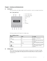
Page 11: ...RT2200RMXL2U SMART2200RMXLN SMART3000RMXL2U SMART3000RMXLN BP48VRM2U BP72VRM2U SMART2200RM2U SMART2200RM2UN SMART3000RM2U SMART3000RM2UN 1 2 3 4 5 6 7 8 9 10 11 12 UPS Input AC power source Primary gr...

Page 12: ...6 Eaton Tripp Lite Series SmartPro User Guide 614 40194 Rev 03 Rear panel...

Page 13: ...e To file a claim for shipping damage or concealed damage 1 File with the carrier within 15 days of receipt of the equipment 2 Send a copy of the damage claim within 15 days to your service representa...

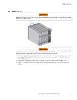
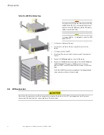
Page 14: ...ails and necessary hardware are supplied by Eaton I In ns st ta alllla at tiio on n iin n t to ow we er r p po os siit tiio on n If you ordered other UPS accessories refer to specific user manuals to...

Page 15: ...Eaton Tripp Lite Series SmartPro User Guide 614 40194 Rev 03 9 Follow steps 1 to 5 to adjust the orientation of the LCD panel and of the logo Figure 2 Tower Installation Steps Recommended Positions...

Page 16: ...igure 3 Internal Battery Connection A small amount of arcing may occur when connecting the internal batteries This is normal and will not harm personnel Connect the cables quickly and firmly 1 Remove...

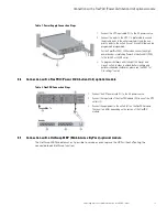
Page 17: ...connecting an EBM to the UPS This is normal and will not harm personnel Insert the EBM cable into the UPS battery connector quickly and firmly 1 Attach the UPS and the EBMs to each other using the sup...

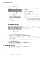
Page 18: ...late to the UPS 4 Place the UPS on the rails and fix the ears plate to the top hole of the rail 5 Connect the EBM power cable as shown in the picture 6 Connect the RJ45 battery detection cable of the...

Page 19: ...ection 3 3 6 6 C Co on nn ne ec ct tiio on n w wiit th h a a F Flle ex xP PD DU U P Po ow we er r D Diis st tr riib bu ut tiio on n U Un niit t o op pt tiio on na all m mo od du ulle e Table 8 FlexPDU...

Page 20: ...is on Bypass the load is supplied directly by the AC power source LED 44 is on Load is not protected 3 3 7 7 1 1 U UP PS S S St ta ar rt t U Up p w wiit th h t th he e H Ho ot tS Sw wa ap p M MB BP P...

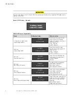
Page 21: ...he indicator status and description Table 12 LED Indicator Details Indicator Status Description Green On The UPS is On and the load is protected Orange On The UPS is in battery mode and the load is pr...

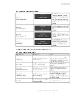
Page 22: ...ndicates the load percentage and VA output load level Load 0 decimals Load VA 0 decimals 3rd Screen Output load power factor LOAD PF x xx UPS MODE The OUTPUT LOAD POWER FACTOR screen indicates the pow...

Page 23: ...nsumed in the last one hour period 2 decimals The following table describes the status information provided by the UPS Table 14 System Operational Status Details Operation status Possible cause Action...

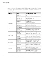
Page 24: ...through this menu SENSITIVITY Sensitivity can be set to high or low through this menu OVRLOAD PREALARM Overload pre alarm can be set through this menu ON OFF SETTING COLD START Cold start can be enabl...

Page 25: ...Main menu Submenu Display information or Menu function OUTPUT DB9 7 Select output signal function for OUTPUT DB9 7 OUTPUT DB9 8 Select output signal function for OUTPUT DB9 8 EVENT LOG Event log has...

Page 26: ...20 Eaton Tripp Lite Series SmartPro User Guide 614 40194 Rev 03 Display Functions...

Page 27: ...e alarms Correct the alarms and restart if necessary 5 Verify that the indicator illuminates solid indicating that the UPS is operating normally and any loads are powered and protected The UPS should...

Page 28: ...ba at tt te er ry y w wa ar rn niin ng g The indicator illuminates solid The audio alarm beeps every three seconds The remaining battery power is low Shut down all applications on the connected equip...

Page 29: ...ot te ec ct tiio on n This setting is recommended to avoid damaging the battery Warranty is void if deep discharge protection is disabled 5 5 7 7 R Re et tr riie ev viin ng g t th he e e ev ve en nt...

Page 30: ...24 Eaton Tripp Lite Series SmartPro User Guide 614 40194 Rev 03 Retrieving the event and fault log...

Page 31: ...s that the batteries charge for 48 hours after long term storage Check the battery recharge date on the shipping carton label If the date has passed and the batteries were never recharged do not use t...

Page 32: ...electrical shock The likelihood of such shock can be reduced if such grounds are removed during installation and maintenance applicable to equipment and remote battery supplies not having a grounded...

Page 33: ...es s To test new batteries 1 Charge the batteries for 48 hours 2 Press any button to activate the menu options 3 Select CONTROL then Start battery test The UPS starts a battery test if the batteries a...

Page 34: ...he load is supplied directly with AC input source power 2 Stop the UPS by pressing the button on the UPS control panel LED 43 UPS ON OK to switch goes OFF the UPS can now be disconnected and replaced...

Page 35: ...ted Verify that all batteries are properly connected If the condition persists contact your service representative Battery fault LED is On Beep continuous The battery test is failed due to bad or disc...

Page 36: ...or Run Time to Empty is below Remaining Time Limit threshold 802 IMMINENT SHUTOFF Shut down imminent 806 EMERGENCY OFF Emergency stop was proceed 808 OVLD PREALARM The load percent is the overload lev...

Page 37: ...e any question or problem with the UPS call Eaton Tripp Lite Series or your local service representative in your country region Please have the following information ready when you call for service Mo...

Page 38: ...32 Eaton Tripp Lite Series SmartPro User Guide 614 40194 Rev 03 Service and Support...

Page 39: ...N SMART2200RM2U SMART2200RM2UN 1950W 1950VA Rack Tower TRIPP LITE SMARTPRO 3000 RTXL2U TRIPP LITE SMARTPRO 3000 RTXL2U NETPACK SMART3000RMXL2U SMART3000RMXLN SMART3000RM2U SMART3000RM2UN 3000W 3000VA...

Page 40: ...ch mm D x W x H BP48VRM2U 61 3 27 8 17 6x17 2x3 4 448x438x85 5 BP72VRM2U 89 1 40 4 23 7x17 2x3 4 603x438x85 5 8 8 4 4 E Elle ec ct tr riic ca all I In np pu ut t Default frequency 60Hz Nominal frequen...

Page 41: ...tr riic ca all O Ou ut tp pu ut t All models Normal mode Battery mode Voltage regulation Boost Vin 1 15 Buck Vin 0 87 10 6 Efficiency 96 750 2200 82 3000 85 Frequency regulation 0 1 Hz Nominal output...

Page 42: ...Specifications 750VA 48Vdc 4 x 12V 7Ah 9Ah max 1000VA 48Vdc 4 x 12V 7Ah 9Ah max 1500VA 48Vdc 4 x 12V 9Ah 2200VA 72Vdc 6 x 12V 7Ah 9Ah max 3000VA 72Vdc 6 x 12V 9Ah BP48VRM2U 48Vdc 2 x 4 x 12V 2 x 9Ah B...

Page 43: ...ating temperature 0 to 40 C 32 to 104 F Storage temperature 15 to 50 C 5 to 122 F Relative humidity 20 to 90 without condensation Operating altitude Up to 3 000 meters 9 843 ft above sea level no dera...

Page 44: ...614 4019403 614 40194 03...

Reviews: