background image

2. HANDLING AND TRANSPORT

If it is not possible to lift using the aforementioned 
methods, rollers may be used underneath the 
switchgear. Another option is to slide the cubicles 
over rods (these same rods can be used to help get 
over the cable pit).

To handle 5 functional unit assemblies (consisting  
of either coupled modules or compact assemblies 
associated with modules), use lifting systems 
(slings, lifting beam, etc.) with a pull  angle  greater  
than  65º and less than 115º in order to prevent 
possible damage to the cubicles during hoisting.

During transport, the switchgear must be perfectly 
seated and fixed so that it cannot move about and 
possibly damage the equipment.

The switchgear must always be kept upright, directly
on the ground or on a pallet depending on the type of
handling involved.

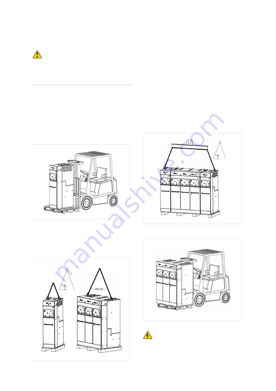
To handle assemblies of up to 5 functional units, one 
of the following methods must be used:

Using a forklift truck or pallet-jack.

Lifting using slings or chains fixed to the lifting 
supports on the sides of the top of the cubicle. The 
angle of pull should be as vertical as possible (with an 
angle greater than 60º from the horizontal).

Lifting of a 

URING

 switchgear with a fork-lift truck

Lifting of a set of 5 

URING

 functional units with lifting beam and chains

Lifting of a 

URING

 switchgear with chains

Lifting of a 

URING

 switchgear with chains

Important!

The use of lifting beams is required for cubicle 
assemblies with control boxes as the sole exception, 
slings or chains may be used if the cubicles of the 
assembly have identical height control boxes installed.

2  

Ulusoy URING36 - LLF - 3 Way Compact Switchgear with Fuse User Manual

 May 2020 www.eaton.com

Summary of Contents for Ulusoy URING36 - LLF

Page 1: ...Ulusoy URING36 LLF 3 Way Compact Switchgear with Fuse User Manual www eaton com ...

Page 2: ... Manual Use and Front Appearance 10 EARTHING SWITCH OPERATION 11 LBS OPERATION 11 SAFE OPERATION 13 REPLACING THE VOLTAGE INDICATOR 14 ELECTRIC TERMINAL SCHEME 14 URING36 F SF6 INSULATED RMU SWITCHGEAR WITH LBS FUSE SWITCHGEAR INTRODUCTION 15 FUSE SELECTION FOR TRANSFORMER PROTECTION 16 PLACING THE FUSES IN THE SWITCHGEAR 17 DIMENSIONS in millimeters 18 Checks Before Energisation the URING36 F Swi...

Page 3: ...hich do not alter or damage the characteristics of the equipment or its essential components Service conditions must be compatible with the equipment rating The equipment must be operated strictly in accordance with the instructions given in the manual and the applicable operating and safety principles must be clearly understood Maintenance should be performed properly taking into account the actu...

Page 4: ...he ground or on a pallet depending on the type of handling involved To handle assemblies of up to 5 functional units one of the following methods must be used Using a forklift truck or pallet jack Lifting using slings or chains fixed to the lifting supports on the sides of the top of the cubicle The angle of pull should be as vertical as possible with an angle greater than 60º from the horizontal ...

Page 5: ...e up to 40 ºC The switchgear must be protected from direct solar radiation Maximum altitude is 2000 m The environmental air must not have any significant contamination from dust smoke corrosive and or inflammable gases vapours or salt Any other conditions must be notified beforehand since the equipment must be factory adjusted to the atmospheric pressure at the final destination or during transpor...

Page 6: ...and one transformer protection unit with fuse combination This is 3 way design URING36 RMU can be designed up to 5 way unit as extensible or non extensible system Switching device in URING 36 is three positioning close open earthed load break switch It has high number of switching operation and high short circuit withstand 1 1 LV Panel 2 Voltage Indicator 3 Manuel Opening Closing Buttons 4 Spring ...

Page 7: ...SORIES 1332 1062 1907 Toroidal Current Transformer LBS LV Compartment Bushing Vacuum CB Protection Relay MV Fuse Single Line Scheme Ulusoy URING36 LLF 3 Way Compact Switchgear with Fuse User Manual May 2020 www eaton com 5 ...

Page 8: ...ront Cover 7 Earthing Switch Operation Hole 8 Operation Order 9 Voltage Indicator Lights 10 Mechanical Assembly Motor Optional 1 LV Control Board Lv Panel 2 Mechanism Section 3 Cable Connection Terminal 4 Cable Connection Clamps 5 Main Busbar Connection Terminals Optional I 5 SWITCHGEAR INTRODUCTION Single Line Scheme 6 Ulusoy URING36 LLF 3 Way Compact Switchgear with Fuse User Manual May 2020 www...

Page 9: ...r 1800 1800 450 860 Check if there are foreign objects in the switchgear Check the connections of the switchgear Check if the front cover is placed correctly Place the switchgear front cover Ulusoy URING36 LLF 3 Way Compact Switchgear with Fuse User Manual May 2020 www eaton com 7 ...

Page 10: ...tch Control Housing Earthing Switch Position Indicator Closing Spring Assembly Housing Remote Trip Control Socket Padlock Key ON I Button OFF I Button Operate the LBS and earthing switch a few times for check After manually assembling load break switch mechanism operate it with buttons a few times LV Board Control Panel of URING36 L 8 Ulusoy URING36 LLF 3 Way Compact Switchgear with Fuse User Manu...

Page 11: ...able test device Test rod as optionally Turn the switch OFF Perform the required test for check the cable healthy Incoming outgoing switchgear To check cable faults insulation Turn the disconnector OFF Switch OFF the power of the switchgear from previous center Turn the earthing disconnector ON Open the switchgear front cover Place the cable test device Turn the earthing disconnector OFF from both...

Page 12: ... LBS is ON Switchgear front cover is open Earthing disconnector is ON LBS is OFF Switchgear front cover is closed At the beginning after the assembly works are finished After closing the switchgear front cover 10 Ulusoy URING36 LLF 3 Way Compact Switchgear with Fuse User Manual May 2020 www eaton com ...

Page 13: ...OFF Earthing switch is OFF Closing spring is not charged LBS is ON Place the operation hole to the hole as shown in the figure and rotate it in arrow direction Ensure that it makes the assembly sound when assembling the closing spring Ifthereisaspringassemblymotorintheswitchgear the spring shall automatically be assembled when the LV fuses MCB ON After the charge of the closing spring Earthing swi...

Page 14: ...N I button OFF 0 button Position of LBS after turning ON Earthing switchis OFF Opening spring is charged LBS is ON To turn the LBS OFF Press the OFF 0 button Position of LBS after turning OFF Earthing switch is OFF LBS is OFF 12 Ulusoy URING36 LLF 3 Way Compact Switchgear with Fuse User Manual May 2020 www eaton com ...

Page 15: ...put the padlock Locking with padlock when earthing switch OFF LBS OFF This lock is used in order to prevent the close the earth switch if the switchgear as incoming switchgear and cable SAFE OPERATION Switchgear front cover can only be removed or attached when the earthing disconnector is ON I I Ulusoy URING36 LLF 3 Way Compact Switchgear with Fuse User Manual May 2020 www eaton com 13 ...

Page 16: ...annot be turned OFF Check if the switchgear front switchgear is correctly placed Remove the switchgear front cover and turn the earthing switch ON LBS cannot be turned ON Check if the earthing disconnector is OFF LBS cannot be operated electrically Check if LV connections are done Check if LV fuses are OFF Check if the earthing switch ON Check if DC auxiliary supply source is charged or not Check ...

Page 17: ...6 Mechanical ON OFF Button 7 Earthing Switch Operation Hole 8 Operation Sequence Label 9 Remote Control Socket 1 LV Board 2 Mechanism Section 3 MV Fuse Housings 4 Cable Connection Terminal 5 Cable Connection Clamps 6 Main Bus bar Connection Terminals Single Line Scheme 6 SWITCHGEAR INTRODUCTION I Ulusoy URING36 LLF 3 Way Compact Switchgear with Fuse User Manual May 2020 www eaton com 15 ...

Page 18: ...al value and fuse adapter FUSE SELECTION FOR TRANSFORMER PROTECTION GÜRAL ELECTRIC MV FUSES SELECTIONTABLE NOMINAL VOLTAGE 33 36 kV TRANSFORMER NOMINAL POWER kVA Uk 4 5 Uk 6 25 50 100 160 250 315 400 500 630 800 1000 1250 1600 FUSE NOMINAL CURRENT In A 2 4 6 3 6 3 10 16 16 16 20 25 30 40 63 INTERTEKNIK MV FUSES SELECTIONTABLE NOMINAL VOLTAGE 33 36 kV TRANSFORMER NOMINAL POWER kVA Uk 4 5 Uk 6 25 50...

Page 19: ...use into the shell place it in the shell by fixing the fuse plug Assemble the MV fuse by placing it in a way that the arrow directs inside the fuse plug Ensure that its clamp is tight Check if the fuse blow assembly on the fuse plug is on the arrow direction according to the plastic piece If the warning lights on the signal light box are on reset the situation by pressing delete button and complet...

Page 20: ... the connections of the switchgear Check if all fuses are placed correctly in all phases Check if the front cover is placed correctly If the front cover is not fixed operation hole cannot be placed in spring charging hole Place the switchgear front cover I I 18 Ulusoy URING36 LLF 3 Way Compact Switchgear with Fuse User Manual May 2020 www eaton com ...

Page 21: ...tor Earth Switch Operation hole Earthing Switch Position Indicator Switching Spring Assembly Housing Operation Order Label Notification Relay Signal Light Box Padlock Key ON I Button OFF I Button Operate the LBS and earth switch a few times URING36 F Switchgear LV Board I I Ulusoy URING36 LLF 3 Way Compact Switchgear with Fuse User Manual May 2020 www eaton com 19 ...

Page 22: ...FF Switchgear front cover is open Earthing Switch is ON LBS is OFF Switchgear front cover is closed At the beginning after the assembly works are finished After closing the switchgear front cover I I I I 20 Ulusoy URING36 LLF 3 Way Compact Switchgear with Fuse User Manual May 2020 www eaton com ...

Page 23: ...e it in arrow direction Ensure that it makes the assembly sound when assembling the closing spring If there is a spring charging motor in the switchgear the spring shall automatically be charge when the LV fuses are ON After the charge of the closing spring Earthing switch is OFF Closing spring is charged LBS is OFF Position of earth switch after turning OFF Earthing disconnector is OFF LBS is OFF...

Page 24: ...osition of LBS after turning ON Earthing switch is OFF Opening spring is charged LBS is ON To turn the LBS OFF press the OFF button Position of LBS after turning OFF Earthing switch OFF LBS is OFF I I I I I I 22 Ulusoy URING36 LLF 3 Way Compact Switchgear with Fuse User Manual May 2020 www eaton com ...

Page 25: ...king with padlock when earthing switch is OFF load disconnector is ON This lock is also used in order to prevent the earthing disconnector from turning on when there is energy in incoming switchgear cables I I SAFE OPERATION Switchgear front cover can only be removed when the earthin switch ON Ulusoy URING36 LLF 3 Way Compact Switchgear with Fuse User Manual May 2020 www eaton com 23 ...

Page 26: ...ing blade ON and OFF a few times while the cover is open While performing this procedure push the earthing disconnector blades downwards with your hand LBS cannot be turned ON Check if the earthing switch is ON LBS cannot be operated electrically Check if LV connections are done Check if LV fuses MCB are OFF Check if the earthing switch is ON Check if DC auxiliary supply source is charged or not C...

Page 27: ...on is to improve the quality of life and the environment through the use of power management technologies and services We provide sustainable solutions that help our customers effectively manage electrical hydraulic and mechanical power more safely more efficiently and more reliably Eaton s 2019 revenues were 21 4 billion and we sell products to customers in more than 175 countries We have approxi...

Reviews: