44
UPS 20-40 kVA, 230/400 V 50/60 Hz output
User’s Guide
1025358
Revision D
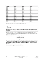
UPS module
Cable A
Cable C
Fuse 1
20 kVA
16 mm²
16 mm²
50 A
30 kVA
16 mm²
16 mm²
50 A
40 kVA
25 mm²
16 mm²
80 A
SPM module
Cable B
Cable D
Fuse 2
20 kVA
16 mm²
16 mm²
50 A
30 kVA
16 mm²
16 mm²
50 A
40 kVA
16 mm²
16 mm²
63 A
50 kVA
25 mm²
16 mm²
80 A
60 kVA
35 mm²
16 mm²
100 A
80 kVA
50 mm²
25 mm²
125 A
90 kVA
70 mm²
35 mm²
160 A
100 kVA
95 mm²
50 mm²
200 A
120 kVA
95 mm²
50 mm²
200 A
150 kVA
120 mm²
70 mm²
250 A
160 kVA
150 mm²
95 mm²
250 A
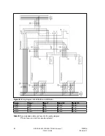
Table 11
Recommended cabels and fuses for the wiring diagram
Note!
Protection fuses need to be used for load cabling if manufacturers SPM (or similar)
not used.
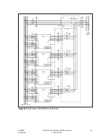
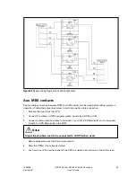
Required parallel system wiring length should be in accordance with the following rule, as
referenced to the diagram below to ensure approximately equal current sharing when in static
bypass mode (see figure below):
Total length of 1A + 1B
= Total length of 2A + 2B
= Total length of 3A + 3B
= Total length of 4A + 4B
This rule has a tolerance of approximately ± 10% for the combined input and output wire lengths.
If installing only two UPS modules (redundant), this requirement is no longer required as each
UPS is capable of supporting the full bypass requirement. However, this would preclude future
expansion.
The recommended length of B cables is 2 m or more.


