UPS 450 - 550 kVA (2x225 - 2x275 kVA)
User’s and Installation Guide
1027574
Revision B
36
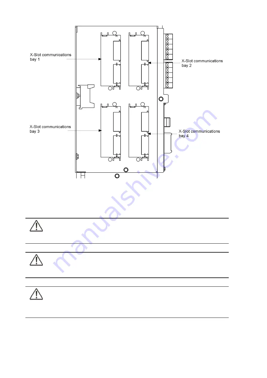
Figure 3-11. X-Slot communication bays
3.6 Installing a remote EPO switch
NOTE
Remove the UPS cabinet interface entry plates to punch holes (see Figure 3-3).
NOTE
This switch must be a dedicated switch not tied into any other circuits.
NOTE
This procedure is intended to be used for the installation of the Powerware remote EPO
switch. If installing another manufacturer’s switch, only use this procedure as a guide.
A remote EPO switch can be used in an emergency to shut down the UPS and remove power
to the critical load from a location away from where the UPS is installed. Figure 3-12 shows a
remote EPO switch.


