83
8 Operating
Mounting and Operating Instructions CEAG Central Battery System ZB-S 40071860179 (L) November 2018 www.ceag.de
Select the system or fault messages on
which relays 1 to 3 change over for sig-
nalling contacts 1 to 3 (“picked up” and
“dropped out” states).
These settings can be used to send infor-
mation about the operational status of the
system to a control centre (e.g. with CEAG
F3 remote indicator).
A standard setting according to DIN VDE
(see Appendix B) can be selected using
the “Load defaults” option at the end of
this menu.
Select the relay number (1 to 3) with
keys
Highlight the events with keys
Select between relay switches (
)
and relay does not switch (no
) with
the <ok> key
Finish and return to Menu 3 with
<Menu>
Activating / deactivating the “Manual
reset” option
(see Menu 2.3 “Manual reset”)
Toggle between “activated” and “de-
activated” with
Finish and return to Menu 3 with
<Menu>
<ok>
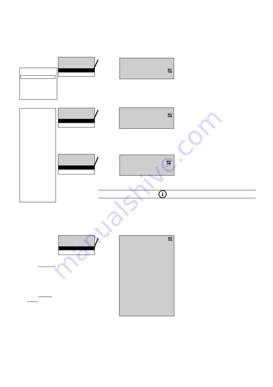
Menu 3.6:
<ok>
Menu 3.8:
Setting the time (1 ... 99 minutes) which
the emergency light remains on after mains
supply is restored.
Select 1 ... 99 minutes with the keys
Finish and return to Menu 3 with
<Menu>
<ok>
Menu 3.5:
Date & time
Functiontest
Durationtest
Delay time mains return
etc....
Functiontest
Durationtest
Delay time mains return
Manual reset
etc....
Delay time mains return
Manual reset
Selective EmgcyOper.
Relay setup
etc....
Manual reset
deactivated
Delay time on mains
return in
minutes 10
Activating / deactivating the “Selective
emerg light” option
Toggle between “activated” and “de-
activated” with
Finish and return to Menu 3 with
<Menu>
<ok>
Menu 3.7:
Durationtest
Delay time mains return
Manual reset
Selective EmgcyOper.
etc....
ote:
N
See also menu option 1.9 “Relay
status” in menu 1 “Test & status
menu”.
Selective emerg light
deactivated
Relays 3
Mains operation
Mains failure
Mains failure MDB
Charge fault
Circuit fault
Luminaire fault
Sum failure
Deep discharge protection
ISO failure
Function test
Battery duration test
DB-FÜB
Device failure
Invert relaycontact
Load defaults
NOTE:
With selective emergency light (only available in conjunction with DLS/3Ph bus mod-
ules) each individual circuit must be assigned to a DLS/3Ph bus module to activate
the emergency light function. See Menu 5.4
The functions «delay on mains return », «manual reset» and «selective emergency
lighting» can be combined on circuits.
Overview:
Main menu
Test & status menu
Block & reset alarms
Basic settings
DLS/TLS Setup
Circuit setup
Luminaire setup
Logbooksetup
Send ServicePinMsg
Menu 3
Language
Date & time
Functiontest
Durationtest
Delay time mains
return
Manual reset
Selective EmgcyOper.
Relay setup
Buzzer setup
Display setup
Charger setup
Printer setup
Relay module setup
Webserver setup
Timer setup
Substation setup
Connection to BMS
Function keys
Optional inputs
Serialnumber & type
Password protection
Daylight saving time
Service info
Selection of
menu options
with the
keys
<ok>:
confirm selec-
tion
<Menu>: can-
cel and return
to the previous
menu (any
changes en-
tered are saved)
<ESC>: cancel
and return to
the previous
menu (any
changes en-
tered are not
saved)
flashing input
prompt
Attention:
Master / Salve mode and CG-
Vision together dosn`t work


