Instruction Book
Effective: May 2016
Page 27
IB131017EN
For more information visit:
www.Eaton.com
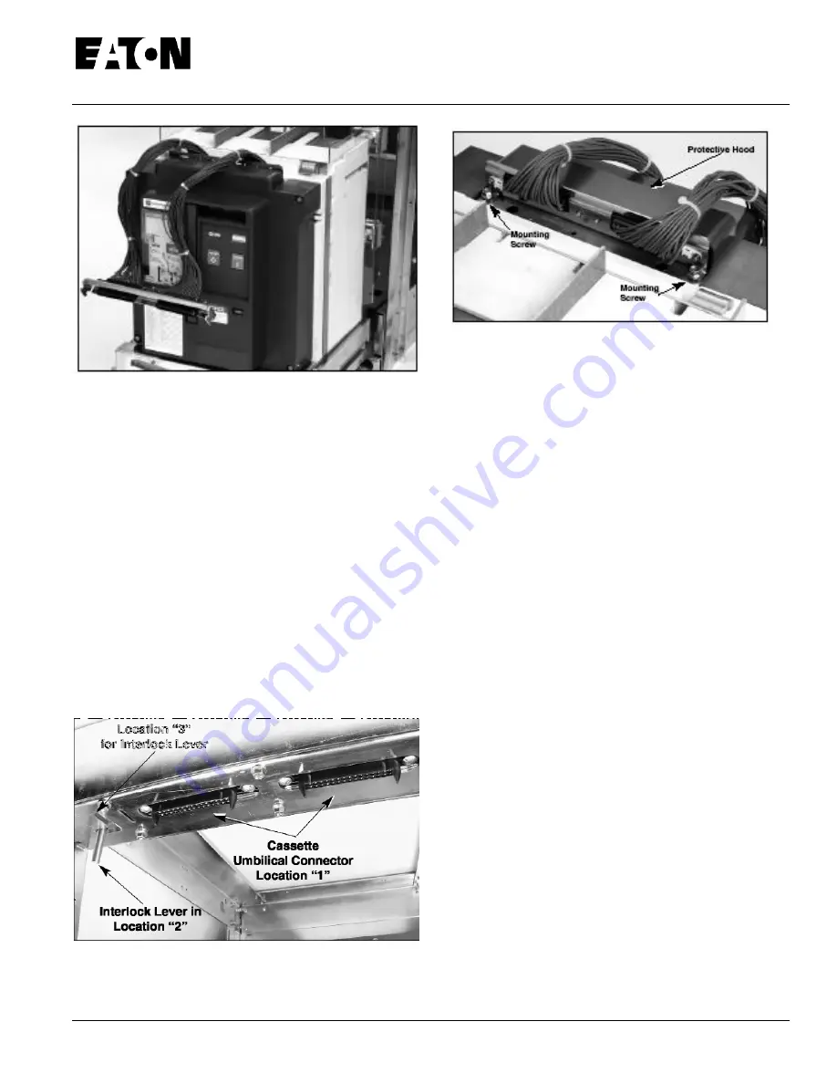
Figure 4-10 Secondary Umbilical Cord Shown
Connected to Breaker Prior to Breaker Insertion
Cassette Secondary Connections
Once the circuit breaker is in position in the cassette as
described in paragraph
4-6.2
with the breaker end of the
umbilical cord properly connected to the breaker, the
cassette end connector of the umbilical cord can be
connect-ed. Once this connection is made, the circuit
breaker will be in its operable TEST position.
To make the cassette's secondary connection, make sure
the shoot bolt handle is in Position
"B"
(Figure
4-8
).
With
the interlock lever in Location
"2"
(back and to left) (Figure
4-12
)
,
take the unconnected cassette end connector of the
umbilical cord (making certain that the connector is
oriented correctly before insertion) and firmly insert it into
its compatible
Figure 4-12 Cassette Secondary Connector and
Interlock Lever
Figure 4-11 Secondary Connector Viewed From Rear of
Breaker
secondary connector at Location "1" on the top front
underside of the cassette (Figure
4-12). Make certain
that the connector on the umbilical cord is completely
inserted into the cassette's connector.
Hold the
connector firmly in place and flush against the underside of
the cassette on all sides with one hand while pulling the
inter-lock lever from Location
"2"
to Location
"3"
(right
and for-ward in keyed slot) (Figure
4-12
)
.
This will lock the
secondary connector of the umbilical cord and the
cassette's secondary connector together.
The shoot bolt handle can now be rotated to its full up
position, Position "C" (Figure
4-7
). In this position the
shoot bolts engage the cassettes interlock plates
completely and the interlock lever cannot be moved back
to Location "2". Since the interlock lever cannot be moved,
the umbilical cord cannot be disconnected from the
cassette. The circuit breaker is now in the TEST position
and ready to be tested mechanically or with secondary
control voltage or ready to be levered to the
CONNECTED position. Refer to paragraph
4-6.4
for
levering details.
To disconnect the umbilical cord from the cassette, the
breaker must be levered to the TEST position and the
shoot bolt handle must be rotated down to Position
"A"
(Figure
4-9
). The interlock lever is once again moved to
Location
"2"
which unlocks the secondary connector
(Figure
4-12).
The cassette end of the umbilical cord can
now be removed from the cassette's connector in Location
"1"
(Figure
4-12).
Since the shoot bolt handle is in
Position
"A"
(shoot bolts fully retracted) and the umbilical
cord is disconnected from the cassette, the circuit breaker
is in the DISCONNECT position and can be removed from
the cassette.
Primary Connections
Primary connections are made when the spring loaded
finger clusters (disconnects) mounted on the rear of the
circuit breaker automatically engage the horizontal stabs
rigidly mounted inside the insulating spouts) at the


