Com
–D.C.
Note
The characteristics of this amplifier are such that once
conduction starts, a very small change in input signal level
will cause a very large change in output current. There-
fore, the 5000 ohm command test potentiometer (shown in
figure 4) will seem to have no effect on the measured out-
put voltage level until the center of the control is reached,
then the voltage level will change rapidly from 0 to –1.5
volts. To obtain –0.6 volts (200 MA) reading, the control
must be varied very slowly when the center of the control
is reached.
5. Connect a volt-ohmmeter between TB2*-2 and TB2*-3
(common ground reference). Apply power and mea-
sure for negative .6 volts (200 MA). The voltage
should vary from approximately zero (0) volts at one
end of the test potentiometer adjustment range to
approximately 1.5 volts at the other. If the amplifier
performs as indicated, it is operating normally.
6. Remove AC power from the system.
7. Connect symbolized wiring removed in step E. 2.
12
11
6
5
7
4
8
3
2
1
3
8
15
7
13
1
2
5
4
6
– D C Supply In
R15
R13
2.2K
R11
Z2
Q4
Q2
D 2
2.7K
R7
1.5 K
Z 4
Z 6
Z 5
Supply Out
R9
1.5 K
R6
Supply Out
2.7 K
R8
Z1
6
5
7
4
8
3
2
1
ALL RESISTORS
+
5%, 1/4 W
UNLESS OTHERWISE SPECIFIED
*FACTORY ADJUST
+D.C.
Z 4
R26
3
Ω
3W
POS
OUT
Q5
R24
470
Ω
R23
3.3K
0.1
µ
f
C2
D3
D4
D5
R25b
R25a
R25
2.0
Ω
3W
Q 6
C5
Summing Junction
Sig. Input 1
R1
DITHER
50K
Sig. Input 2
DITHER
+ D.C. Supply In
+1%,5W
R2
5K
+1%
5 W
R16
15K
R10
R12
R14
Q3
2.2K
220
Ω
D1
Q1
D8 D9
A
1
R17
22K
R271%1/10W
a
*
R3
10 K
R2
C4
.0068
µ
F
200K
R4 a
GAIN
R 4
470PF
R18
1 K
R20a
R20
82 K
*
DITHER
R21
3.3K
A2
NEG
OUT
D 6
*
*
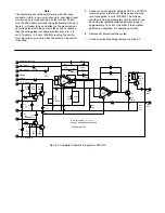
Figure 1. Complete Schematic Diagram for EM-A-10
68
Ω
220
Ω
68
Ω
b


