10
Torque Motor Coil
Location
Color Code Versus
Connector Pin
Location
Red
Coded
Coil “A”
A
B
Coil “B”
Coil located next to the
armature connection nut
D
C
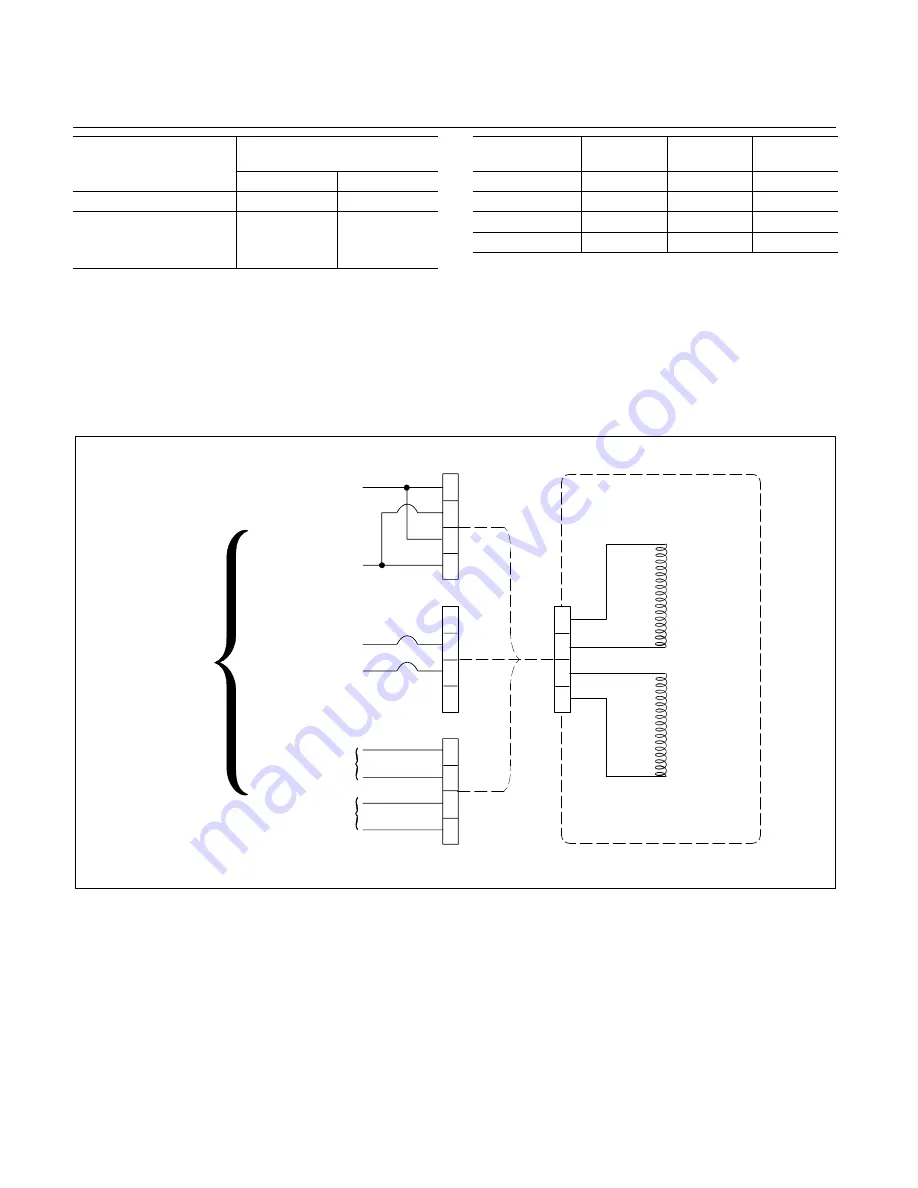
Table 4. Coil location and wiring code to male electrical connec-
tor (Item 4, Figure 3).
7. Remove a
1
/
4
inch of insulation from the ends of the
wires, then install a short piece of spaghetti sleeve over each
wire end and slide back on the wire. Position the wire ends up
and slide a new gasket (5) over the wires. Tin each wire end
with solder, then insert wires one at a time into the proper pin
of connector (4) and solder. Slide the sleeve over the pin after
solder has cooled.
Coil resistance,
ohms/wire code
Series
aiding
Parallel
Differential
40 / Yellow
150 ma
300 ma
N/A
280 / White
50 ma
100 ma
100 ma
2200 / Blue
20 ma
40 ma
40 ma
5300 / Black
12.5 ma
25 ma
25 ma
Table 5. Input current required for max. armature deflection of
0.020 inch.
8. Assemble connector to the body with four screws. (3).
NOTE
Cover (7), screws (8), and washers (9) will be
installed following test and calibration, Section VII.
A
B
C
D
A
B
C
D
A
B
C
D
A
B
C
D
TORQUE MOTOR
MALE CONNECTOR
A
– Red
B
– Coded
C
– Coded
D
– Red
Coil “B”
(Next to
armature
nut)
CABLE
+
–
–
+
–
+
+
–
PARALLEL
CONNECTION
SERIES
AIDING
CONNECTION
DIFFERENTIAL
CONNECTOR
POWER
SUPPLY
Polarity for
movement of
armature nut
in direction
of arrow
stamped on
torque motor.
NOTE: Reversal
of supply will
reverse
movement of
armature.
Figure 5. Schematic diagram of possible wiring connections to a Torque Motor.


