background image

12

2

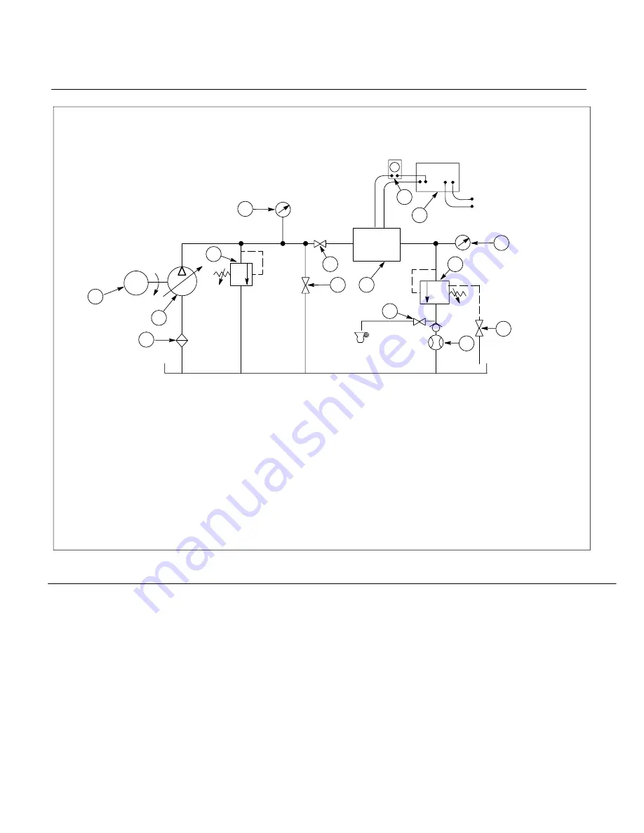
Beaker

1.

Globe valve

2.

Test stand relief valve

3.

Inlet filter

4.

Variable delivery pump

5.

Pressure gage (0–3500 psi)

6.

Globe valve

7.

Valve under test

8. Ammeter (0–500 mA)
9. Power supply Vickers 631995 or

equivalent. Must be capable of
delivering 0–300 mA DC to a
20 OHM inductive load.

10. Pressure gage (0–3000 psi)
11. Load relief valve

12. Globe valve
13. Flow meter
14. Electric drive motor approximately

10 hp for 5 gpm @3000 psi

15.

1

/2

 Globe valve

16. 35 psi check valve

Figure 6. Test stand for FCGT-02-*-11 valve

M

6 7

2 1

Printed in U.S.A.

11

14

4

3

5

1

6

7

8

9

10

12

13

15

0-500mA

Meter

117 VAC 60

Power

Source

Gage

0–3000

Pump

System

Relief

Valve

Gage

0–3500

IN

OUT

Vent

Summary of Contents for Vickers FCGT-02-A-004-11

Page 1: ...I 3419 S Reprinted 6 1 96 Remote Flow Control Valves FCGT 02 A B 11 S30 Overhaul Manual Vickers Flow Controls...

Page 2: ...Installation Drawing 5 B Mounting 5 C Piping and Tubing 5 D Hydraulic Fluid Recommendations 5 E Overload Protection 5 V Service and Maintenance 6 A Inspection 6 B Adding Fluid to the System 6 C Adjust...

Page 3: ...ariations within each basic model series are covered in the model code Table 2 is a complete breakdown of the model codes covering these units Service inquiries should always include the complete unit...

Page 4: ...ow Control Valve as being two distinct and separate systems one a standard compensated flow control with a fixed throttle setting and secondly an electrically modulated device torque motor used to var...

Page 5: ...g wire brushing and pickling NOTE For instructions on pickling refer to instruction sheet 1221 S 2 To minimize flow resistance and the possibility of leakage only as many fittings and connections as a...

Page 6: ...ed Sophisticated design processes and materials are used in the manufacture of our parts Substitutions may result in early failure Part numbers are shown in the parts listing reference Figure 3 F Prod...

Page 7: ...es 4 Symbolize each wire with a piece of tape to allow reassembly to the same pin of the connector Unsolder the four wires from connector 4 Remove connector and gasket 5 NOTE Hold the valve over a con...

Page 8: ...Ring O Ring Screw Elect Connector Gasket Screw Cover Screw Lockwasher Torque Mtr 280 Ohms Torque Mtr 2200 Ohms Torque Mtr 5300 Ohms Torque Mtr 40 Ohms Spacer Spool wire screw S A Spool wire screw S A...

Page 9: ...luded in the following steps See Figure 3 1 If nameplate 32 was removed install a new name plate with four screws 31 2 Install parts 29 through 24 into body 30 If seat 27 or check valve 26 were defect...

Page 10: ...resistance ohms wire code Series aiding Parallel Differential 40 Yellow 150 ma 300 ma N A 280 White 50 ma 100 ma 100 ma 2200 Blue 20 ma 40 ma 40 ma 5300 Black 12 5 ma 25 ma 25 ma Table 5 Input curren...

Page 11: ...il 3000 PSI is read on gage 5 and globe valve 1 is completely closed d Open globe valve 6 NOTE Valve may be unstable until all air is purged from the system Allow at least one minute for valve to stab...

Page 12: ...delivering 0 300 mA DC to a 20 OHM inductive load 10 Pressure gage 0 3000 psi 11 Load relief valve 12 Globe valve 13 Flow meter 14 Electric drive motor approximately 10 hp for 5 gpm 3000 psi 15 1 2 G...

Reviews: