3
Section I – Introduction
A. Reference Material
Installation dimensions and operating specifications are not
contained in this manual. Refer to installation drawing
501170 for that information.
B. Kits
A gasket kit is available for this servo valve. It is recom-
mended that new O-Rings and gaskets be used during
overhaul. The part number of the kit is 919529.
x 100 Equals Supply Pressure in psi
3
5
1
3
4
5
1
2
2
Table 1. Model Code Breakdown
Servo Valve, series, 4-way
x 0.1 Equals Flow Rate in gpm
Model Series
Design No. & Modification
4
Coil Designation - number
x 10
Equals Coil Resistance in Ohms
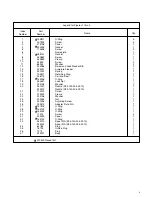
Figure 1. Exploded View of Servo Valve
30
6
7
5
8
9
36
29
25
24
23
19
18
21
13
12
31
32
33
34
37
1
2
3
4
17
22
16
20
15
14
27
35
28
26
11
10
Pilot
Stage


