


9
15kV Class Padmount VisoVac™
instruction manual
MN024004EN April 2021
ote:
N
For all other relay styles, third-party CTs will be
provided based on user specifications. Please see
the
“Appendix”
for associated product literature
and switchgear wiring schematics for details. See
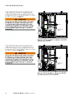
Figure 19
for equipment access detail.
Potential Transformer (PT)
Potential transformers can be used as a voltage measuring
device and/or control power source when capacity allows.
PTs are provided by third-party suppliers. Please see the
“Appendix”
for associated product literature and switchgear
wiring schematics details. See
Figure 19
for equipment
access detail.
Space heaters/thermostats
Generally, space heaters are provided to assist in
controlling condensation and temperature to maintain inside
temperature of the switchgear. Please see the
“Appendix”
for associated product literature and switchgear wiring
schematics for details. See
Figure 19
for equipment access
detail.
Surge arresters
Standard surge arresters provided with the VisoVac
switchgear are manufactured by Eaton. Please see the
product link below and the
“Appendix”
for switchgear
wiring schematics for details. See
Figure 19
for equipment
access detail.
https://www.eaton.com/us/en-us/products/medium-voltage-
power-distribution-control-systems/lightning-arresters.html
Engineered-to-Order
All switchgear is based on application requirements.
Switchgear can come with unique protection and control
systems designed specifically for that application. Please
review all mechanical diagrams, layout drawings, electrical
schematics, and accessory-specific documentation for
details in the
“Appendix”
section of this document.
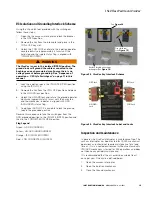
Access panels
The VisoVac switchgear comes standard with access panels.
Access panels are bolted panels that allow users to gain
access to the internals of the switchgear. These panels will
allow users to access some of the accessories previously
listed including fusing for control power and instrument
transformers. The following are examples of access panels.
Users should reference the mechanical layout drawings of
the equipment provided for associated details.
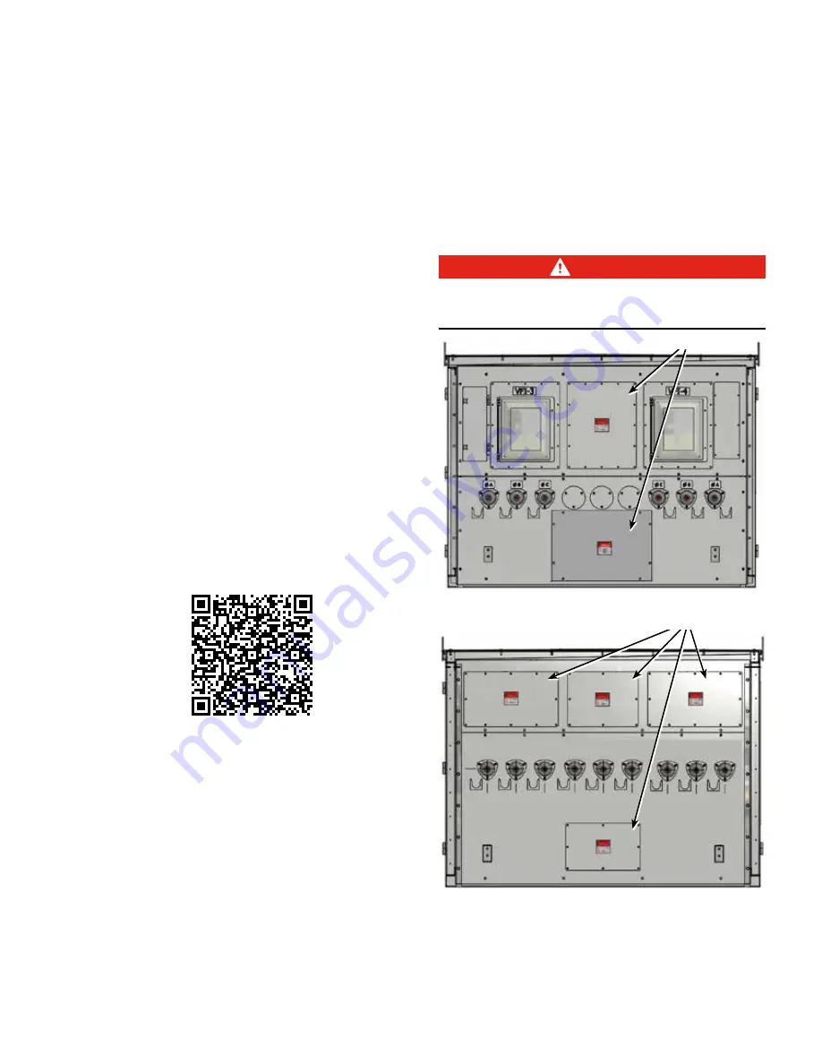
DANGER
The switchgear must be fully deenergized and local
lock-out tag-out and associated safety procedures must
be followed prior to removing the access panels .
Access panels
Access panels
Figure 19 . Remove access panels


