background image

16

15kV Class Padmount VisoVac™  

instruction manual

   MN024004EN   April 2021

ote: 

N

It may not be possible to complete steps 3 and 

4 without de-energizing the upstream device. In 

this case, step 3 and 4 can be skipped.

4.  Open the Ground mechanism.
5.  Close the Isolation mechanism.
6.  Close the vacuum interrupter.
It is recommended not to remove any covers from the 

VisoVac interrupter while the assembly is in service. If any 

fasteners are loosened, the quality of the enclosure will be 

compromised. If any repair is necessary, it is recommended 

that the assembly be taken out of service and moved into 

a controlled maintenance environment. If any cover is 

removed for maintenance, new gasketing is required for 

reassembly. The following list provides a list of cleaning, 

testing and maintenance tasks for the vacuum interrupter 

and related equipment.


Operation of breakers: After step 1 above, clean VCPT as 

per the linked manual. 

https://www.eaton.com/content/dam/eaton/products/

electrical-circuit-protection/medium-voltage-vacuum-

circuit-breakers/mv-vcp-t-vacuum-circuit-breakers/vcp-t-

vcp-tr-instruction-book-ib131016en.pdf


Heaters/thermostats: Heathers and thermostat shall be 

cleaned after opening of interrupter. 


Dielectric testing: Once the unit has left the factory 

and been placed in service, subsequent dielectric tests 

performed during maintenance should be performed at 

75% of the rating per IEEE recommendation.


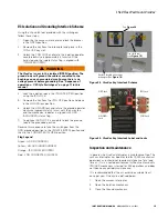
Follow these steps to perform the Pre-Startup inspection: 


Inspect the equipment visually. 


Make sure all connections are tightened and all covers 

are closed before moving to next step.


Make surroundings neat and clean to prevent trip-and-

fall injuries.

Safety features

There are several safety interlocks built into the VisoVac 

assembly to ensure the proper sequence of operations.
1.  Vacuum interrupter to Isolating mechanism interlock 

(V3 designs only)
a.  The vacuum interrupter is mechanically interlocked 

with the Isolating mechanism.

b.  The vacuum interrupter will not close unless the 

isolating rods are in the fully connected position.

c.  If a tool is placed on the isolating rod mechanism, 

the vacuum interrupter will trip open before any 

electrical contact is broken.

2.  Isolation mechanism to ground mechanism

a.  The isolating mechanism is mechanically 

interlocked with the ground mechanism.

b.  When the isolating rods are in the connected 

position, the ground rods are blocked from moving 

and remain blocked until the isolating rods are in 

the fully open position.

c.  When the ground rods are in the connected 

position, the isolating rods are blocked from 

moving and remain blocked until the ground rods 

are in the fully open position.

3.  Ground mechanism to upstream device

a.  It is imperative that there be no voltage present on 

the cable bushings before closing the ground rods.

b.  Since this requires opening the upstream device 

that may be blocks or even miles away, it is 

recommended that the user deploy their Lock-out/ 

Tag-out and/or operational procedures to ensure no 

voltage is present before closing the ground rods.

4.  Arc reduction maintenance system (ARMS) 

(Digitrip 1150V only)
a.  When the Arcflash Reduction Maintenance System 

is enabled, the internal digital logic is bypassed by 

a “faster than instantaneous” analog trip circuit 

based on user preset values. In this mode, the 

Digitrip is set to hair trigger and issues subcycle 

tripping. Total clear is estimated within 4 cycles. 

b.  Eaton’s Arcflash Reduction Maintenance System 

technology is based on the realization that when 

working on energized electrical equipment, a fault 

that occurs within the gear or downstream needs 

to be cleared as quickly as possible. While this 

seems obvious, in actual installations, intentional 

delays are included in upstream devices to ensure 

selective coordination with downstream devices. 

This means that if a fault were to occur inside the 

equipment the downstream breaker may never 

clear the fault regardless of how much delay is or 

isn’t programmed in the upstream device. While 

other Eaton Arcflash technologies are available, the 

Arcflash Reduction Maintenance System comes 

standard with the Digitrip 1150 V. This patented 

technique provides “faster than instantaneous” 

clearing times.

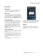
See the following link for literature on the Digitrip 1150V 

ARMS functionality: 

https://www.eaton.com/content/dam/eaton/products/

electrical-circuit-protection/medium-voltage-vacuum-circuit-

breakers/mv-vcp-t-vacuum-circuit-breakers/digitrip-1150v-

with-maintenance-mode-il66a7535.pdf

Summary of Contents for VisoVac

Page 1: ...15kV Class Padmount VisoVac instruction manual Network Protectors MN024004EN Effective April 2021 New Issue ...

Page 2: ...POSE OR MERCHANTABILITY OTHER THAN THOSE SPECIFICALLY SET OUT IN ANY EXISTING CONTRACT BETWEEN THE PARTIES ANY SUCH CONTRACT STATES THE ENTIRE OBLIGATION OF EATON THE CONTENTS OF THIS DOCUMENT SHALL NOT BECOME PART OF OR MODIFY ANY CONTRACT BETWEEN THE PARTIES In no event will Eaton be responsible to the purchaser or user in contract in tort including negligence strict liability or otherwise for a...

Page 3: ...TION 3 Terminations 3 Mounting 3 Control voltages 4 V1 AND V3 SWITCHGEAR STYLES 5 V1 Vacuum interruption only 5 V3 Vacuum interruption with visible isolation and visible grounding 6 Accessories 7 SEQUENCE OF OPERATIONS V1 STYLE SWITCHGEAR 10 SEQUENCE OF OPERATIONS V3 STYLE SWITCHGEAR 11 Source way operation example 11 SEQUENCE OF OPERATIONS V3 STYLE SWITCHGEAR 13 Load way operation example 13 V3 I...

Page 4: ...hich if not avoided will result in death or serious injury WARNING Indicates a potentially hazardous situation which if not avoided could result in death or serious injury CAUTION Indicates a potentially hazardous situation which if not avoided may result in minor or moderate injury NOTICE Indicates a potentially hazardous situation which if not avoided may result in equipment damage only Safety i...

Page 5: ...pt inspect the shipping container crate for signs of damage Unpack the switchgear and inspect it thoroughly for damage incurred during shipment If damage is discovered file a claim with the carrier immediately Handling and storage Be careful during handling and storage of the padmount switchgear to minimize the possibility of damage If the switchgear is to be stored for a long time prior to instal...

Page 6: ...Vac switchgear is specifically designed with a higher interrupting rating and higher operations CAUTION Before energizing the VisoVac assembly ensure that 1 The VisoVac assembly is secured on a true and level surface 2 All fastening hardware is in place and tightened 3 All conductor connections are torqued to the correct value Ratings and specifications Table 1 General Specifications Feature 25 kA...

Page 7: ...vided in double sided or single sided layout designs The following figures show the features of each of these designs Controls Bushings Figure 4 Control front Cable rear design Controls are located in front and switchgear bushings are located in the rear of the enclosure Controls Bushings Figure 5 Controls and bushings located on same side Applies to both double sided and single sided designs In s...

Page 8: ...voltages The switchgear is available in most commonly used AC and DC voltages for control power and comes pre wired to reduce on site field installation time Users should reference the electrical wiring schematics for details on the specific control and auxiliary voltages used in the equipment Note that in some cases two different voltages may be used one class for protection and another for heate...

Page 9: ...ts The load break mechanism is available with up to a 900 A continuous current rating and comes with a mechanical endurance of 10 000 operations The three phase vacuum interrupter can be opened manually or remotely via SCADA protective relaying or pendant The vacuum interrupter is equipped with a mechanical indicator and non resettable operations counter Eaton vacuum interrupters are the industry ...

Page 10: ... any conditions Indicators are physically linked to the operating mechanism and show what position the isolation switch is in The isolation switch is mechanically interlocked internally with the vacuum interrupting load break mechanism The isolation switch is also mechanically interlocked internally with the grounding switch to prevent the grounding switch from being operated while the isolation s...

Page 11: ...e VisoVac Eaton Digitrip 1150 V Controller Eaton s Digitrip 1150 V is used for advanced current and voltage protections metering and communication functions The Digitrip 1150 V comes standard with energy harvesting overcurrent protection capability During loss of power or voltage sag from a fault the Digitrip can use the energy of the fault to maintain protection and initiate a trip in the absence...

Page 12: ...ure 18 V3 Switchgear control schematic with Digitrip Eaton CH Type current sensors are provided on ways using the Digitrip 1150 V CH Type sensors come standard with 1 A secondaries and are available with the following primary current ratings 100A 200A 250A 300A 400A 6060A 630A 800A 1000A 1200A For more information about the Digitrip 1150 V please see the following link https www eaton com content ...

Page 13: ...e product link below and the Appendix for switchgear wiring schematics for details See Figure 19 for equipment access detail https www eaton com us en us products medium voltage power distribution control systems lightning arresters html Engineered to Order All switchgear is based on application requirements Switchgear can come with unique protection and control systems designed specifically for t...

Page 14: ...epresents energized bus and green represents de energized bus LOAD BUS SW 1 Source Loads VFI 1 VFI 2 VFI 3 Figure 20 MODEL 9 V1 Single Line Diagram VFI 1 SW 1 Loads Source Figure 21 V1 style padmount All ways CLOSED In this position the vacuum interrupters are OPEN Example assumes all load ways VFI 1 are de energized with no load side sources and SW 1 is the only source way SW 1 is OPEN however th...

Page 15: ...e not shown The example assumes no load side sources In this position the vacuum interrupter and the visible isolation rods are CLOSED The grounding position is OPEN and the isolation rod is energized This example assumes all ways are energized See Figure 24 LOAD BUS SW 1 Source VFI 1 VFI 2 VFI 3 Loads Figure 23 MODEL 9 V3 Single Line Diagram Isolation Rod CLOSED Ground ROD OPEN Load Bus Source SW...

Page 16: ...s considered de energized Isolation Rod OPEN Ground ROD OPEN Source SW 1 OPEN Load Bus Figure 26 V3 style padmount Isolation position Open In this position the vacuum interrupter and visible isolation rods are OPEN The grounding position is CLOSED This example assumes all ways are OPEN and internal load bus is de energized See Figure 27 WARNING The ground rods will ground the cables connected to t...

Page 17: ...bushings any control power sources or stored energy devices such as capacitors must be de energized discharged before gear is considered de energized LOAD BUS SW 1 Source VFI 1 VFI 2 VFI 3 Loads Figure 28 MODEL 9 V3 Single Line Diagram Load Bus Isolation Rod CLOSED Ground ROD OPEN Loads VFI 1 CLOSED Figure 29 V3 style padmount Source and load ways CLOSED In this position the vacuum interrupter is ...

Page 18: ...d Bus Isolation Rod OPEN Ground ROD OPEN Load VFI 1 OPEN Figure 31 V3 style padmount Load ways and visible isolation rods are OPEN In this position the load way vacuum interrupters and visible isolation rods are OPEN The grounding position is CLOSED This example assumes all load ways VFI 1 are de energized and there are no load side sources The source way SW 1 is closed See Figure 32 WARNING The g...

Page 19: ...proximately 4 turns until the hard stop and the mechanical indicator is aligned with GRD GROUNDED status flag 7 An optional GRD LOCK is available to lock the ground rods in the grounded position Reverse this sequence to take the switchgear from the GRD grounded position to the ISOLATE OPEN position and then to the CONNECTED CLOSE position Flag Legend Green GRD GROUNDED Yellow UN GRD UNGROUNDED Ora...

Page 20: ...pen before any electrical contact is broken 2 Isolation mechanism to ground mechanism a The isolating mechanism is mechanically interlocked with the ground mechanism b When the isolating rods are in the connected position the ground rods are blocked from moving and remain blocked until the isolating rods are in the fully open position c When the ground rods are in the connected position the isolat...

Page 21: ...cations with seamless integration into the user s central control system Supports secure DNP3 MODBUS and INCOM protocols Please see the Appendix for equipment specific drawings schematics and component details Automatic transfer control Eaton s ATC 900 brings intelligence adaptability supervisory and programming capabilities to automatic transfer switch equipment Extreme reliability makes the ATC ...

Page 22: ...esha WI 53188 United States Eaton com cooperpowerseries 2021 Eaton All Rights Reserved Printed in USA Publication No MN024004EN April 2021 Eaton is a registered trademark All trademarks are property of their respective owners For Eaton s VisoVac product information call 1 877 277 4636 or visit www Eaton com SAFETY FOR LIFE ...

Reviews: