3
15kV Class Padmount VisoVac™
instruction manual
MN024004EN April 2021
Features and Construction
The VisoVac fault interrupter utilizes a stored-energy spring
charged mechanism for OPEN and CLOSE operations. The
gear comes standard with a spring charging motor on all
VFI (Vacuum Fault Interruption)-ways with optional spring
charge motors for all switched-ways. Each way comes with
OPEN and CLOSE pushbutton controls and spring charge
indication.
Terminations
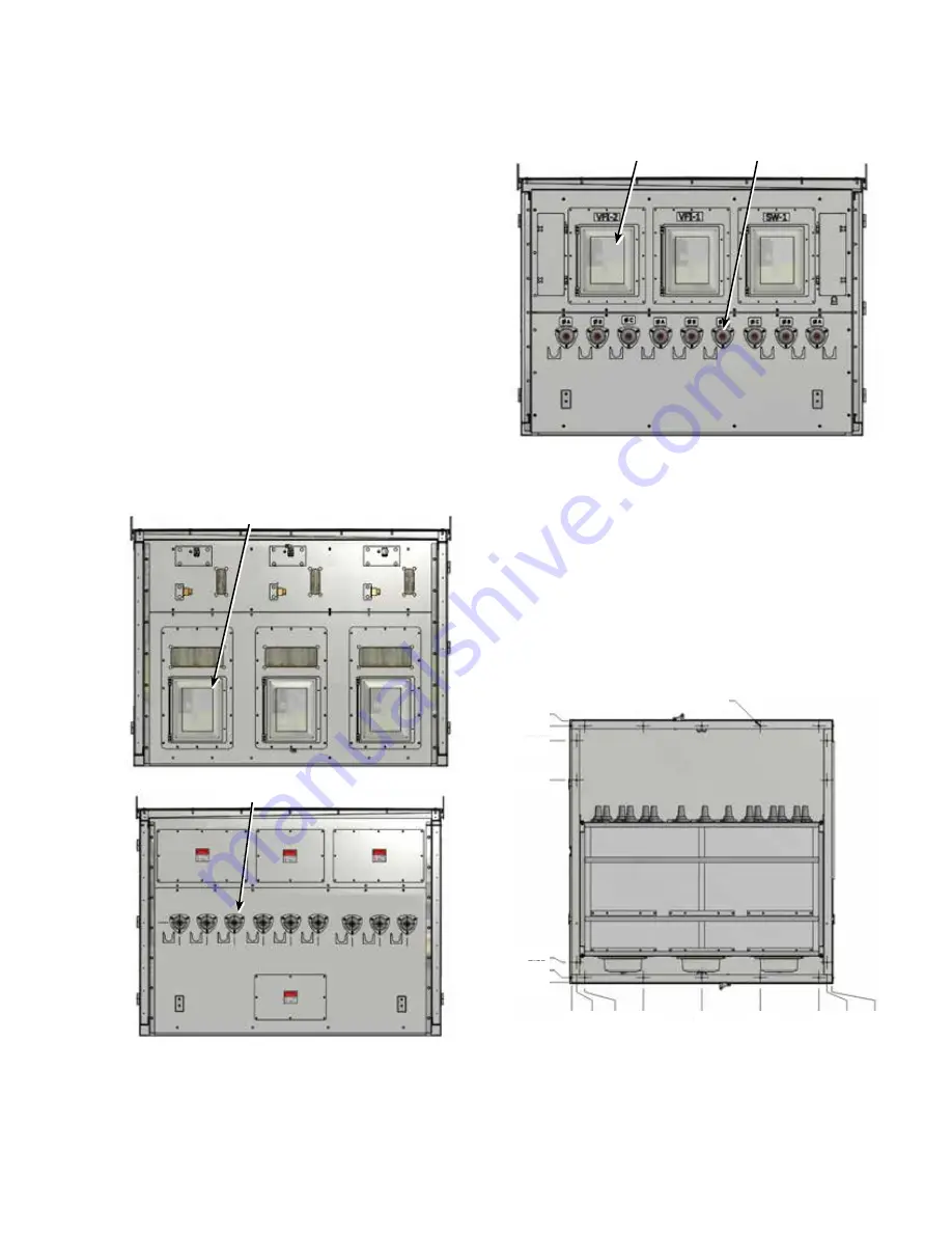
Standard padmount terminations are IEEE 386 600 A
deadbreak elbow style bushings mounted in the rear of
the padmount enclosure on the opposite side of breaker
controls. This is also known as Eaton’s Control front/Cable
rear design (see
Figure 4
). Eaton also offers designs with
the bushings and breaker controls on the same side (see
Figure 5
). This style switchgear can be provided in double-
sided or single-sided layout designs.
The following figures show the features of each of these
designs.
Controls
Bushings
Figure 4 . Control front/Cable rear design . Controls are
located in front and switchgear bushings are located in
the rear of the enclosure .
Controls
Bushings
Figure 5 . Controls and bushings located on same side .
Applies to both double-sided and single-sided designs .
In some cases, 600 A to 200 A reducers are provided if load
break elbows are required.
Mounting
The switchgear can be mounted directly on the floor or
concrete pad. The switchgear is suited for indoor or outdoor
applications. Users should reference the mechanical
drawings provided with the switchgear for location of the
base mounting points associated with that equipment. The
following are common examples of location and spacing for
the base mounting.
Base mounting Ø.56 (16 Total)
80.00
79.50
73.99
61.99
5.99
1.50
.00
.0
0
1.
50
4.0
0
22.0
0
40.0
0
58.0
0
76.0
0
78
.5
0
80.0
0
Figure 6 . Control front/Cable rear base mounting
(dimensions in inches)


