
1
2
3
4
5
6
7
8
9
10
11
12
13
14
15
16
17
18
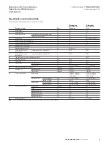
Technical Data
TD534-0501002U
Instructions for the Installation,
Operation and Maintenance
of W-SLC-7.2
Effective January 2013
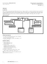
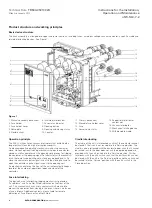
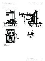
Product structure and working principles
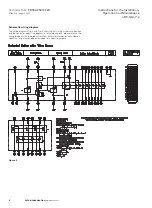
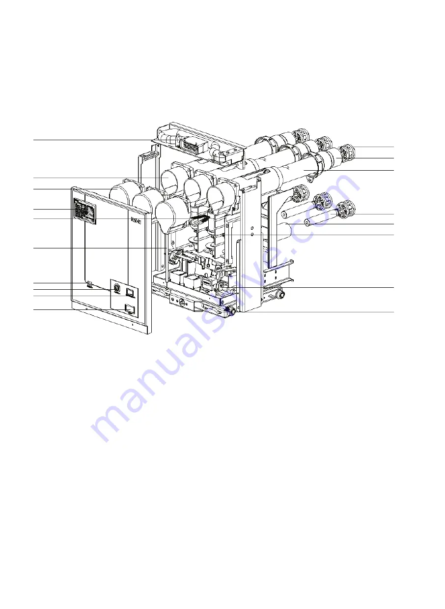
Basic device structure
The truck assembly is arranged into upper and lower sections, including fuses, a medium voltage vacuum contactor, a specific cradle and
related interlocking devices. See Figure 1.
1. Manual secondary disconnect
2. Fuse holder
3. Fuse holder cover
4. Nameplate
5. Flexible shunt
6. Insulated interlock bar
7. Fuse status indicator
8. Opening button
9. Opening and closing status
10. Counter
11. Primary disconnect
12. Movable fuse holder cover
13. Fuse
14. Lower contact arm
15. Support plate for lower
contact arm
16. Vacuum interrupter
17. Mechanical latching device
18. Withdrawable cradle
Figure 1
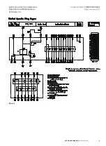
Operation principle
The W-SLC utilizes Eaton vacuum interrupters that exhibit both a
long electrical life and a high interruption capability.
An electromagnetic operating mechanism makes the contactor
close, while an optional latching mechanism keeps the contactor
closed as well as compresses the opening spring ready for tripping
the contactor at the opening signal. For contactors with mechanical
latch, there are two operating coils, closing and opening coils. To
close the contactor a pulse signal is sent to the closing coil and to
open the contactor a pulse signal is sent to the opening coil.
An electronic counter on the front of the unit automatically keeps a
record of the number of operations (open and close) of the
contactor.
Cradle interlocking
The cradle of the unit is interlocked such that the contactor cannot
be closed if the truck is not racked into the ‘Service’ position. The
cradle is also interlocked with the enclosure door such that it cannot
be racked in with the door open nor can the door be opened are
provided with the unit racked into the ‘Service’ position. Further
interlocks with the earth switch such that the earth switch cannot
be closed with the unit in the ‘Service’ position and the unit cannot
be racked into the ‘Service’ position with the earth switch in the
Closed position.
Fuse interlocking
The device has an interlocking tripping mechanism to provide
‘Fuse Blown’ and ‘Fuse Not Fitted’ indication on the front of the
unit. This mechanism has auxiliary contacts which are used to
prevent the contactor from closing in the event there is no fuse or
a fuse is blown. Additional contacts are available for remote
indication of Fuse Blown or Fuse Not Fitted.
3
EATON CORPORATION
www.eaton.com


