Technical Data
TD534-0501002U
Instructions for the Installation,
Operation and Maintenance
of W-SLC-7.2
Effective January 2013
Commissioning and operating
The W-SLC has completed full factory tests and inspection before
being packed. Packing materials provide maximum protection and
convenient handling to the equipment during shipment .
BEFORE THE W-SLC IS PUT INTO USE, PLEASE FOLLOW THE MOUNTING
PROCEDURES STRICTLY. OTHERWISE, SHIPPING DAMAGE CAUSED
DURING TRANSPORTATION WILL NOT BE DETECTED AND THUS COULD
RESULT IN A MALFUNCTION OF THE UNIT IN THE FUTURE, WHICH MAY
CAUSE PERSONAL INJURY OR EQUPIMENT DAMAGE.
3. Storage
If the W-SLC is required to be stored before being put into use, it
should be stored in its original packing materials for maximum
protection. Before storage, examine the unit for any shipping damage,
Store the unit ONLY indoors in a clean, dry, well ventilated area to
avoid moisture condensation. If the indoor storage facility is not dry,
heaters should be provided to avoid condensation.
1. Initial check and operation
Before mounting the W-SLC, please carefully examine the unit for
any loose or damaged parts. Please check whether the unit’s
nameplate is in accordance with switchgear. If not, contact Eaton
immediately. Upon completion, insert the unit into the switchgear
and follow procedures 4.2.3 below.
2. Inspection of fuses
For most applications, fuses have already been installed before the
W-SLC is ready for shipment. Inspection is needed to see whether
fuses are damaged during transportation. For replacement and
mounting of fuses, please refer to relevant rules in Clause 5.6.
3. Pre-engineering operations
Before the W-SLC is moved into the switchgear, check whether
there are items within the panel which will prevent proper
operation.
The W-SLC has been inspected before delivery. Below preparations
shall be conducted before primary circuits are energized:
1) Before cradle operation, check whether cradle interlocks are
working. Do not use undue force, to avoid any damage to the
interlock mechanism:
a. Interlock mechanism is used to prevent from turning the
W-SLC cradle racking handle when the contactor closed;
b. Interlock mechanism is used to prevent contactor from
closing before the cradle is racked into the ‘Service’ position
or testing position
c. Interlock mechanism is used to prevent the racking handle
operating with the door open.
d. Interlock mechanism is used to prevent the compartment
door opening with the unit in the ‘Service’ position.
2) Connect the secondary connector and apply secondary power
and operate the contactor according to procedures. Then check
whether opening and closing position indicator is working
properly
3) Move the cradle from ‘Test’ position to ‘Service’ position,
according to below procedures:
Close the compartment door and ensure all bolts are tightened.
Ensure that the Earth Switch is ‘Open’. Insert the cradle racking
handle into the cradle socket. Turning in a clockwise direction to
rack in (into ‘Service’ position) while turning in a
counterclockwise direction to rack out (into ‘Test’ position). The
total cradle racking travel from testing position to service
position is about 200mm. If all the interlock conditions to prevent
the cradle from moving have been met, turn the handle 20 cycles
in a moderate speed. When it clicks (the sound when position
switch inside the cradle operates), it means it’s in the correct
position. Do not use excessive force as this may to damage on
the operating mechanism. At this moment, the corresponding
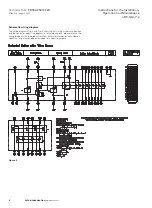
position indicator (S8, S9) circuits are closed to indicate correct
position of the unit within the switchgear.
WARNING
NOTICE
ENSURE THAT FUSES ARE MOUNTED IN A CORRECT ORIENTATION.
7
EATON CORPORATION
www.eaton.com
Mounting, commissioning and operating
Receiving, handling and storage
The W-SLC has completed full factory tests and inspection before
being packed. Packing materials provide maximum protection and
convenient handling to the equipment during shipment .
1. Receiving
Maintenance and testing of the W-SLC shall only be carried out
when the unit is removed from the panel and placed on a stable
workbench.
Examine the W-SLC for any signs of shipping damage such as
broken, missing or loose fastenings, damaged insulators or other
deformed parts. If damage or loss is detected, please claim
immediately with the carrier and notify Eaton.
2. Handling
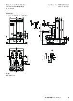
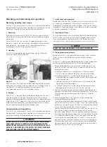
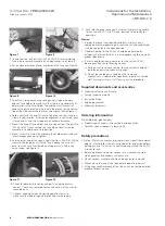
The W-SLC is equipped with special lifting lugs for lifting and
transport. Please refer to Figure 5.
Figure 5
Figure 6
After transport, the lifting lugs on both sides need to be removed
before the unit is ready to be inserted into the switchgear. Please
see Figure 6. For detailed procedure for racking into the
switchgear please refer to the switchgear manual.


