
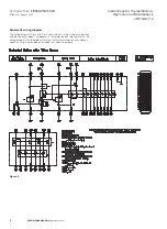

Technical Data
TD534-0501002U
Instructions for the Installation,
Operation and Maintenance
of W-SLC-7.2
Effective January 2013
Inspection of vacuum interrupter
During routine inspection, check visually whether the external surface
of vacuum interrupter is clean. If there is dirt and other items present
then clean the bottles.
Inspection of contact’s wear-out
The contactor's vacuum contacts have a very long electrical life.
Usually, it only needs to be replaced after 300,000 operations.
A new contactor’s over-travel is 2mm. With the contact wear the
over-travel decreases. If contact wear is excessive a replacement
Vacuum interrupter can be installed into the contactor, It is
recommended that all 3 vacuum interrupters are replaced at the
same time. Check with the SL Contactor Operating Manual
ALL OPERATIONS AND MAINTENANCE WORK FOR THE W-SLC SHALL BE
CONDUCTED ON THE CONDITION THAT THE PRIMARY CIRCUIT IS NOT
LIVE. ONCE THE DEVICE IS POWERED ON, IT CAN CAUSE DANGER SUCH
AS ELECTRICAL SHOCK OR FIRE. USE PROPER VOLTAGE TRANSFORMERS
OR VOLTMETERS TO TEST VOLTAGE, IN ORDER TO ENSURE THAT THE
DEVICE IS NOT LIVE.
DANGER
WARNING
Maintenance
The W-SLC operates on certain conditions. Its maintenance period
depends on different factors such as surrounding environment and
operating cycles. Only experienced maintenance staff should be
permitted to conduct maintenance or inspection of the unit.
Usually, the device should get a complete inspection and check
every 50,000 operations or once a year, whichever occurs first.
The W-SLC must be stored in a clean place away from dirt and other
contaminants. Vacuum cleaners or blowers should be used to
remove dirt from the W-SLC.
Check for any loose connections for overheating or discoloration.
Check whether the insulation is damaged due to high temperature.
When checking fastening pieces, the screw torque should not be too
high as this could strip the threads. Hold each wire and pull
moderately, to check whether the wiring terminals are fastened.
HIGH VOLTAGE TESTING DANGER. PAY ATTENTION TO SAFETY!
Keep the contactor in open status, conduct the power frequency
withstand voltage test at 20kV maintain 1min across the open gap,
phenomena such as break down and discharging is not allowed.
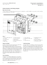
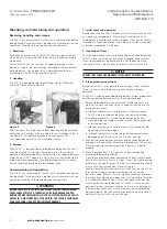
Inspection of mechanisms
First, make visual inspection for any loose accessories and parts
including nuts and bolts. Then, inspect the W-SLC for any worn out
or damaged parts. Rack the W-SLC in and out several times, to
ensure smooth operation. All the parts which need lubrication are
lubricated before shipping. However if the lubricants have
degraded it may be essential to lubricate the parts during annual
inspection.
Usage of fuses
Before putting into use, check the fuse appearance for completeness,
wellness, cleanness and correct mounting direction. The striker pin
should be facing the front of the unit.
An interlocking tripping mechanism is fitted within the fuse holder
cover. When only one phase fuse blows, it will cause the contactor
to open. Similarly, if one phase fuse is not installed, the interlock
mechanism will prevent the contactor from closing.
In the event that the W-SLC experiences a 3 phase fault it may be
that only one fuse will blow due to the difference in actuation times
of each fuse and that the contactor will open when a single fuse is
blown. In this case even though the two remaining fuses appear to
be in good working order, the three fuses should all be replaced
together, due to overcurrent in the remaining fuses may have
permanently altered the tripping characteristics of the remaining
fuses.
Replacement of fuses
After the W-SLC fuse operates or goes through short circuit fault
current, the fuse should be replaced, to make sure that the unit
can work properly. All three phase fuses should be replaced at the
same time, unless there is enough evidence indicating that fault
current has not gone through a certain phase fuse – in case of a
single phase fault. To replace the fuses, below procedures should
be followed:
1. Ensure that the W-SLC cradle is in Test’ position, the contactor
is in OFF status. Remove the cradle from the panel and put it
into the transfer cart;
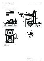
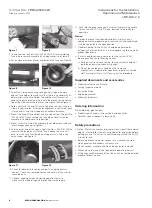
2. Use an inner hexagon spanner to remove the screws which
fasten movable fuse holder cover, see Figure 7;
8
EATON CORPORATION
www.eaton.com
4. Troubleshooting:
NO.
Phenomenon
Causes
1
2
Not able to close
Cradle not able to be racked in/out
1. The contactor is already in closed status
2. The cradle is not fully into the fully connected or test positions
3. The firing pin in the fuse is already ejected out
4. Secondary circuit of the panel is not correct
1. The contactor is closed
2. Cradle racking handle is not fully engaged
3. Check that the shoot bolts on both sides of the front of the cradle. Make sure they are correctly
engaged in the side of the panel. If the shoot bolts are not engaged correctly then the racking
handle will be locked and unable to turn.
4. The circuit earth switch is in the ON position will prevent the cradle from being racked in.
Note:
Please check based on above causes. Contact the manufacturer if problems still exist.


