background image

xChargeIn

Read off device information and meter reading

Manual for MID variants V1.01

16

© EATON

Trigger information display via brightness sensor

To trigger the information display, the brightness sensor must be covered
("dark") and illuminated ("light") in a defined sequence. Each state ("dark" or
"light") must last between 1 and 5 seconds.

Sequence: 

Dark > Light > Dark > Light > Dark

The states ("dark" or "light") can be generated using a flashlight. The flash-
light is placed directly in front of the sensor and switched on and off in the
defined sequence.

5.3

Information display

The following information is displayed one after the other. The displayed in-
formation must be checked for correctness, in order to accept the meter
reading as valid.

Display

Description

1.

Suitability of the firmware confirmed by type examination

2.

Firmware version

3.

Build version associated with the firmware version

4.

Checksum of the firmware

5.

Display of meter reading: Sum of total transmitted energy
in kWh

6.

Summary of Contents for xChargeIn

Page 1: ...EATON xChargeIn Electric Vehicle Charging Station Manual for MID variants V 1 01 Translation of the original instructions...

Page 2: ...Pages 28 EATON Specifications are subject to change due to further technical developments Details presented may be subject to correction All rights reserved Eaton Industries Austria GmbH Eugenia 1 394...

Page 3: ...2 4 Overview of MID variants 10 3 Display 11 3 1 Display 11 3 2 Brightness sensor 12 4 Active power meter 13 4 1 Measurement principle 13 4 2 Non return device 13 4 3 Operational readiness 14 5 Read o...

Page 4: ...es an imminently hazardous situation which will result in death or se rious bodily injury if the corresponding precautions are not taken WARNING indicates a potentially hazardous situation which can r...

Page 5: ...ion authorities and simi lar institutions Persons who due to their special training expertise and experience as well as knowledge of current standards are able to assess the work performed and the pos...

Page 6: ...ion Operation of the charging station Description of the operation of the charging station as an active power meter according to MID 2014 32 EU 1 5 Further documentation Designation Target group Opera...

Page 7: ...poses in accordance with the European Measuring Instruments Di rective MID 2014 32 EU The MID variants have an active power meter certified energy meter and are specifically indicated on the type plat...

Page 8: ...uch on the type plate Position of the type plate The type plate is located on the left at the top of the charging station Fig 2 1 Top view Position of the type plate 1 Type plate Information on the ty...

Page 9: ...ght screw of the front part with the housing cover removed The meter seal has the following number on it 3002 2073 1 Front part 2 Meter seal Information If the meter seal is removed you must assume th...

Page 10: ...nation EVC x xxxxx3xxx Charging stations with an active power meter are available in the following variants Product designation example EVC S 32 S 2 R 3 3 4 0 Product x Device series x S Series S M Se...

Page 11: ...tus e g software version IP address authorization request The main task however is to display the status of the internal energy meter During periods of inactivity the display brightness is reduced and...

Page 12: ...xChargeIn Display Manual for MID variants V1 01 12 EATON 3 2 Brightness sensor The brightness sensor is located on the front of the charging station on the left below the LED bar 1 Brightness sensor...

Page 13: ...principle The measurement of the transmitted energy takes place by means of pas sive transducers on all phases to be contacted Fig 4 4 Measurement scheme 1 Mains supply to the supply termi nals 2 Pow...

Page 14: ...4 3 Operational readiness The active power meter is active in all available operating modes in which power can be delivered including commissioning mode and MID test mode See 6 1 Behavior of the charg...

Page 15: ...ts such as charging cable charging connector or charging socket Sufficient period of validity of the calibration according to the calibration plate The information is visible on the type plate after i...

Page 16: ...ight can be generated using a flashlight The flash light is placed directly in front of the sensor and switched on and off in the defined sequence 5 3 Information display The following information is...

Page 17: ...arging station be checked In MID test mode the energy transferred from the charging station is dis played directly on the charging station display The resolution of the dis played energy is 0 1 Wh In...

Page 18: ...se LED 4 Charging socket a Test probes energy source b Evaluation unit for pulse LED c Test probes sink A test device is connected to the charging station for the measurement On the input side the tes...

Page 19: ...al behavior of the energy source in the test device The pulse LED flashes with 10 000 light pulses per kilowatt hour The display shows the total energy in 0 1 Wh Wh Segment S3 on the LED bar lights up...

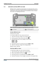
Page 20: ...aids Jumper To activate the MID test mode proceed as follows 1 Switch off the supply voltage of the charging station 2 Set the jumper on the pin strip for the jumper X6 3 Set the DIP switches for the...

Page 21: ...01 21 EATON 5 Switch on the supply voltage of the charging station MID test mode is deactivated 6 3 Affixing the calibration plate The calibration plate must be affixed so that it is clearly visible...

Page 22: ...n the required knowledge The following target groups are distinguished User of a charging station U Electrician E Service technician S Charging station operators O Calibration authority C Possible int...

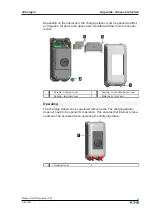
Page 23: ...are provided with their own access pro tection 1 Screws housing cover 2 Sealing connection panel cover 3 Sealing terminal cover 4 Meter seal front part Operating The charging station can be operated...

Page 24: ...ection panel cover by means of a seal Opening the connection panel cover allows access to important interfaces and configuration settings located in the connection panel Ethernet USB in terface servic...

Page 25: ...rician can secure the terminal cover by means of a seal Internal components of the charging station and the active power meter are still protected by the non removable front part An attempt at manipul...

Page 26: ...ess sensor 12 16 C Calibration 17 Calibration plate 21 Calibration validity 15 D Display Position 11 I Information display 15 M Meter reading 15 MID test mode 17 Activate Deactivate 20 Behavior of the...

Page 27: ......

Page 28: ...Eaton Industries Austria GmbH Eugenia 1 3943 Schrems Austria www eaton com evc...

Reviews: