Chapter 2.2.1. – 11
EATON CORPORATION
xxxxx+xxxx-xxxxEN
Residual Current Devices
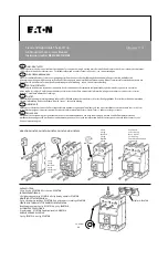
Dimensions (mm)
Local Indication RCCB
Status indication LED
red / yellow / green
Permanent light green
Normal operation
Permanent light yellow
The measured residual current is bigger than 30% of the nominal trip-
ping value.
Permanent light red
The measured residual current is bigger than 50% of the nominal trip-
ping value.
Flashing yellow/red
Check the device with test key. If the LEDs are still flashing check the
direction of connection (supply side / load side).
Remote Indication
Potential-free auxiliary switch for use in control circuits, insulated from main circuit of the switch gear according to IEC/EN60664.
0.25A ohmic load / 240V AC, terminal capacity: 0.25 - 1.5 mm
2
.
Correct connection
2-pole
(240V)
Netzseite
Lastseite
3+N
(240/415V)
Netzseite
Lastseite
3-phase application
(30mA 184-264V)
(300mA 184-415V)
Netzseite
Lastseite
Test button works within 184-264V (30mA) bzw. 184-440V (300mA)!
- Disconnect load side of the switch gear, if you make a insulation test of the installation!
- Please take care of supply side and load side!
Load side
Supply
side
Load side
Supply side
Load side
Supply
side
4-pole
(240/415V)
Load side
Supply side


