7 Guidelines for station planning
7.3 Power supply
XI/ON: XNE-GWBR-2ETH-MB
10/2011 MN05002008Z-EN
www.eaton.com
145
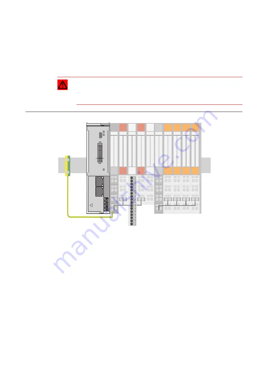
C-rails can be used for a common voltage supply (24 V DC) when relay modules are planned.
To accomplish this, the load voltage is connected to a power feeding module with the
XN-P4x-SBBC base module. All the following relay modules are then supplied with power via
the C-rail.
Cross-connecting relay module roots is achieved by the use of jumpers. The corresponding
wiring diagram including the jumpers can be found the following manual:
• MN05002010Z
User Manual XI/ON
Digital I/O-Modules, Supply Modules
7.3.5
Direct wiring of relay modules
As well as the options mentioned above, relay modules can be wired directly. In this case,
base modules without C-rail connections should be chosen to guarantee the potential isolation
to the adjoining modules.
Attention
When relay modules are planned and the C-rail is used for a common voltage supply,
a further power supply module must be used for the potential isolation to the follow-
ing modules. The C-rail can only again be used as a PE following potential isolation.
Figure 71:
Using the C-rail
as protective
earth and for the
power supply
with relay mo-
dules
23
22
21
13
12
11
23
23
22
22
21
21
13
13
12
12
11
11
24
23
22
21
14
13
12
11
TS
SBBC
2 DO
SBC
8 DI
ECO 2 DO
SBC
2 DI
SBB
C-rail (PE)
PE
PF
1
2
3
4
5
6
7
8
9
10
11
12
13
14
15
16
24
23
22
21
14
13
12
11
24
23
22
21
14
13
12
11
24
23
22
21
14
13
12
11
24
23
22
21
14
13
12
11
24
23
22
21
14
13
12
11
PF
NC
NO
SBCS
SBCS
NO
SBCS
NC
SBCS
C-rail (24 V DC)
SBBC
GW
IOs
SERVICE
0
1
ADDRESS
20
21
22
23
24
25
26
27
MODE
CFG
off
on
MS
Unlock
end-bracket
befor
e
dismounting
Slide
top
cover
for
configuration
and
service
UL
GNDL
USYS
GNDSYS
!
ETH1
ETH2


