9 Appendix
9.1 Data image of the technology modules
168
XI/ON: XNE-GWBR-2ETH-MB
10/2011 MN05002008Z-EN
www.eaton.com
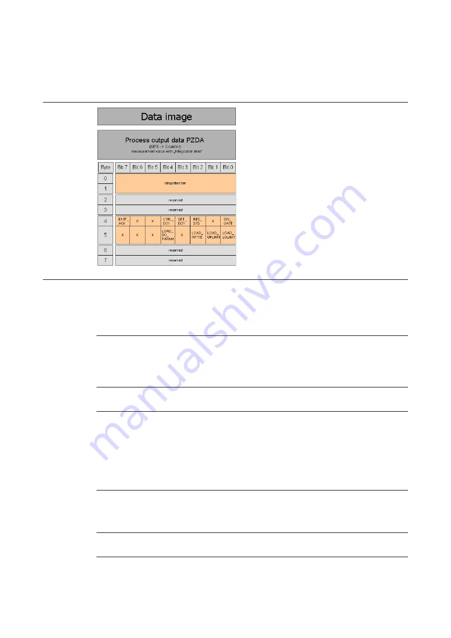
Structure of the data bytes with "Integration time set"
Figure 81:
Structure of the
data bytes with
"Integration
time set"
Table 79:
Process output
data - measure-
ment mode of
XN-1CNT-
24VDC
Control bit
Value, meaning
EXTF_ ACK
Error acknowledgement
The ERR_DO or ERR_24Vdc error bits must be acknowledged with
the control bit EXTF_ACK after the cause of the fault has been
rectified. This control bit must then be reset again. Any new error
messages are not set while the EXTF_ACK control bit is set!
CTRL_DO1
– 0: The output DO1 is blocked.
– 1: The output DO1 is released.
SET_DO1
If CTRL_DO1 = 1 and the physical output DO1 is configured for
indicating the value SET_DO1, DO1 can be set and reset directly
with SET_DO1.
DO1 can be set for this function via the process output
(MODE_DO1 = 00 and LOAD_DO_PARAM 0
→
1).
The output DO1 can also be set before commissioning via the
separate parameter data. The default setting for DO1 is to display
the value of SET_DO1.
RES_STS
0
→
1: Initiate resetting of status bits. The STS_UFLW, STS_OFLW
and STS_CMP1 (process input) status bits are reset. Bit
RES_STS_A = 1 (process input) acknowledges that the reset
command has been received. RES_STS can now be reset to 0.
SW_GATE
0
→
1: Measuring is started (software release).
1
→
0: Measuring is stopped.


