5 Implementation of Modbus TCP
5.9 Parameters of the modules
82
XI/ON: XNE-GWBR-2ETH-MB
10/2011 MN05002008Z-EN
www.eaton.com
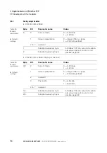
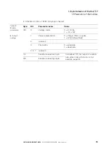
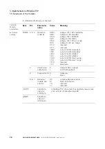
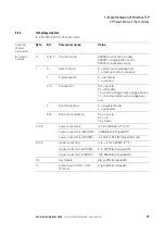
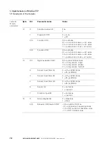
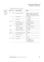
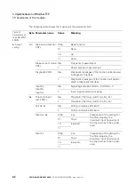
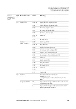
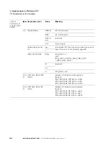
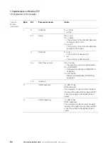
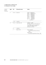
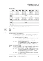
The following table shows the meaning of the parameter bits:
Table 31:
Parameters of
the XNE-2CNT-
2PWM
Byte Parameter name
Value
Meaning
A
Default-
setting
0,3
Main count direction
CNTx
00
A
Basic function
01
None
10
Up
11
Down
Measurement mode
CNTx
0
A
Frequency measurement
1
Period duration measurement
Diagnostic CNTx
0
A
Diagnostic messages of the function unit activated
in diagnostic interface
1
Diagnostic messages of the function unit deacti-
vated in diagnostic interface
Input Zx,
Input Bx,
Input Ax
0
A
Signal logic remains (LOW = 0 / HIGH = 1)
1
Invert signal before processing
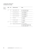
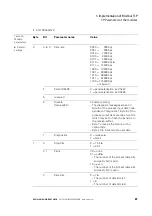
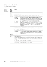
1,4
Threshold input
A,B,Z CNTx
0
A
Threshold 7.5V (only valid for Ax, Bx, Zx)
1
Threshold 2.5V (only valid for Ax, Bx, Zx)
Pull Up Zx
0
A
Pull Up resistance 20 k
Ω
off
1
Pull Up resistance 20 k
Ω
on
Filter Ax, Bx
00
A
2
μ
s
Irrespective of the setting for
the filter property, the
maximum input frequency of
the channel has to be consid-
ered
01
16
μ
s
10
reserved
11
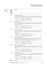
Filter Zx
00
A
2
μ
s
Irrespective of the setting for
the filter property, the
maximum input frequency of
the channel has to be consid-
ered
01
16
μ
s
10
reserved
11


