5 Implementation of Modbus TCP
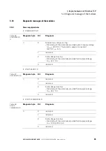
5.10 Diagnostic messages of the modules
XI/ON: XNE-GWBR-2ETH-MB
10/2011 MN05002008Z-EN
www.eaton.com
97
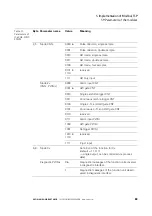
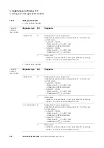
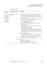
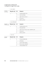
• XN-1AI-U(-10/0...+10VDC)
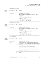
• XN-2AI-U(-10/0...+10VDC)
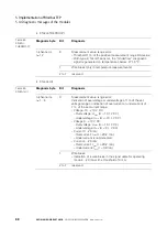
• XN-2AI-PT/NI-2/3
Table 41:
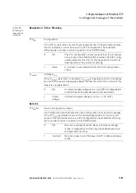
XN-1AI-U
(-10/0...+10VDC
Diagnosis byte
Bit
Diagnosis
n (channel 1)
0
Measurement value range error:
Indication of overvoltage or undervoltage of 1% of the set
voltage range.
– Voltage -10…+10 V DC:
– Overvoltage: U
max
(U > 10.1 V DC)
– Undervoltage: U
min
(U < -10.1 V DC)
– Voltage 0…+10 V DC:
– Overvoltage: U
max
(U > 10.1 V DC)
– Undervoltage: U
min
(U < 0.1 V DC)
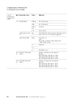
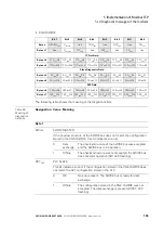
Table 42:
XN-2AI-U
(-10/0...+10VDC
Diagnosis byte
Bit
Diagnosis
n (channel 1)
0
Measurement value range error:
Indication of overvoltage or undervoltage of 1% of the set
voltage range.
– Voltage -10…+10 V DC:
– Overvoltage: U
max
(U > 10.1 V DC)
– Undervoltage: U
min
(U < -10.1 V DC)
– Voltage 0…+10 V DC:
– Overvoltage: U
max
(U > 10.1 V DC)
– Undervoltage: U
min
(U < 0.1 V DC)
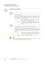
n + 1 (channel 2)
0
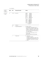
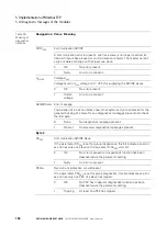
Table 43:
XN-2AI-PT/NI-
2/3
Diagnosis byte
Bit
Diagnosis
n (channel n),
n=1,2
0
Measurement value range error:
– Unterflow diagnostics only in temperature measurements
– Threshold: 1 % of the positive measurement range limit value
1
Wire break
2
Short-circuit (only in temperature measurements):
– Threshold: 5
Ω
(loop resistance)
– With 3-wire measurements with PT100 sensors, no distinc-
tion is made between short-circuit and wire break at a temper-
ature below -177 °C. In this case, the “Short-circuit” diag-
nostic signal is generated.
3 to 7
reserved

