3. Installation
3.5 Preparing the device for operation
3.5.2.1 Power supply Panel-PC, Terminal and Terminal with Extender RX
XP-504-10-...,XP-504-15-...,XP-504-21-... and XP-504-..-TERMINAL-EXT
+24 V DC
0 V
U
e
= 24 V DC
(18 - 36 V DC SELV)
I
e
= ...
0 V +24 V DC
0.5 - 0.6 Nm
(4.4 - 5.3 lb-in)
XP-504-..-TERMINAL
+24 V DC
0 V
U
e
= 24 V DC
(12 - 32 V DC SELV)
I
e
= ...
0 V +24 V DC
0.5 - 0.6 Nm
(4.4 - 5.3 lb-in)
0 V
+24 V DC
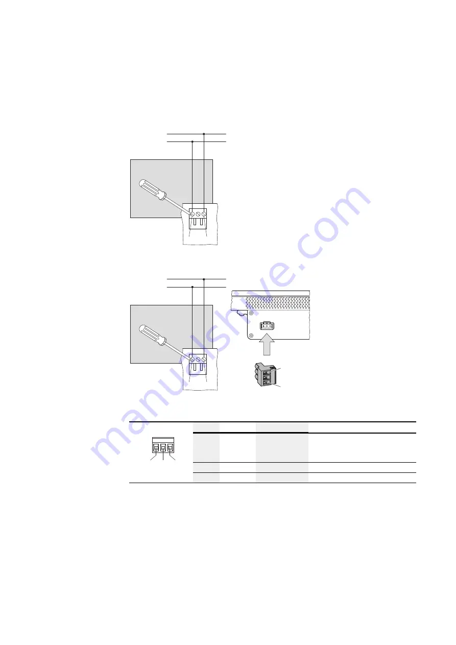
Fig. 21: Connecting the screw terminals with MSTBT 2.5/3-ST-5.08
PIN
Signal
Connection
Configuration
0 V
+24 V DC
n.c.
1
+
24 VDC
Power Supply
+ 24 VDC SELV (safety extra low
voltage)
2
n.c.
not used
3
-
0 V
0 V power supply
Tab. 11: ConfigurationMSTBT 2.5/3-ST-5.08
64
XP-504
04/2022 MN048028EN Eaton.com
Summary of Contents for XP-504-10-A10-A01-2B
Page 1: ...Manual 04 2022 MN048028EN XP 504 Manual...
Page 4: ......
Page 86: ...5 Commissioning 5 2 Running the XP 504 86 XP 504 04 2022 MN048028EN Eaton com...
Page 98: ...7 Operating System 7 2 Windows 10 Enterprise LTSC 98 XP 504 04 2022 MN048028EN Eaton com...
Page 100: ...8 Faults 100 XP 504 04 2022 MN048028EN Eaton com...
Page 130: ...Appendix A 2 Further usage information 130 XP 504 04 2022 MN048028EN Eaton com...

