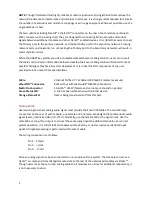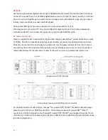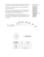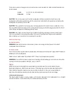
18
10.
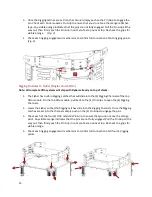
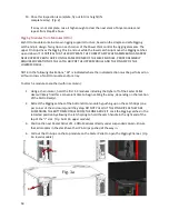
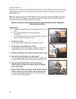
Once this inspection is complete, fly out to trim height (if a
complete array).
(Fig. 4)
If array is not complete, raise it high enough to clear the next stack of Anya modules and
repeat from Step #2 above.
Rigging Modules from Modules (Otto)
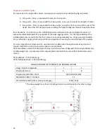
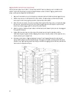
Each Otto module contains its own rigging support structure, based on the simple and safe Rigging
Latch-and-pin design. Two grips on each corner of the Power Plant control the rigging elements. The
upper Pin Grip drives the Rigging Pins in and out while the lower Latch Grip moves the Rigging Latches
up and down. IT IS CRITICAL THAT USERS OPERATE THE CORRECT GRIP WHEN ASSEMBLING AN ARRAY.
NEVER OPERATE BOTH GRIPS ON THE SAME CORNER OF THE SAME MODULE. PROPER ASSEMBLY
REQUIRES OPERATION OF THE LATCH GRIP OF THE UPPER MODULE AND THE PIN GRIP OF THE
LOWER MODULE.
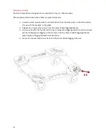
NOTE: In the following illustrations, “X4” is indicated where the indicated action must be performed on
all four corners of an Otto module and/or array.
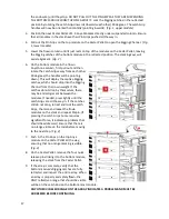
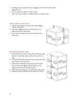
To attach a module to another (within a column):
1.
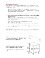
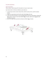
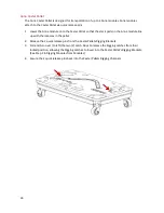
Using a chain motor, hoist the first 1-3 modules including the Flybar off of the Caster Pallet.
User will likely find this a convenient time to begin cabling the array, depending on the location
of the Distro Rack(s).
2.
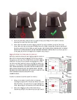
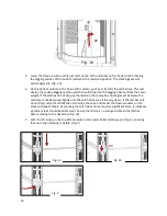
Retract the Rigging Latches of the bottom Otto module by pushing up on the Latch Grips (one
per corner of the enclosure) until they stop. DO NOT PULL OUT THE PIN GRIPS AS THEY ARE
SUSPENDING THE BOTTOM MODULE FROM THE ONE ABOVE IT. Lock the Rigging Latches in the
retracted position by allowing the latch spring to hold the Latch handle in the right end of the
top of the “L” slot.
(Fig. 1a & 1b, upper module)
3.
Position the next Caster Pallet of 1-3 Otto Modules directly under suspended column. Ensure
that all modules in the stack have their Pin Grips pushed all the way in.
4.
Pull out the Pin Grips on the top module on the Caster Pallet to open the Rigging Channel.
(Fig.
1a, lower module)
X4
X4
Fig. 1a
Summary of Contents for ADAPTive systems
Page 1: ...Accessory Rigging Guide...


