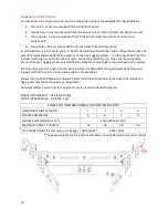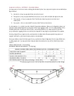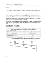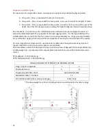
5
NOTE:
Though field-tested and highly reliable, multicore junctions carrying Ethernet data reduce the
network’s resistance to interference and data loss. In all cases, it is strongly recommended to minimize
the number of extensions and multicore couplings used in a given system. Wherever possible, use of a
single extender is best.
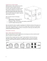
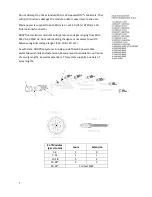
The two, identical, locking Neutrik® etherCON™ connectors on the rear of each module combine an
RJ45 connector with a locking shell. They are designed for connecting Ethernet audio and control
signals between additional modules and other Dante™ enabled devices. It is critical that users connect
the Primary port to the primary network, and the Secondary port to the secondary network. Crossing
network ports and networks (i.e. connecting the Primary port to the Secondary network) will result in
communication errors.
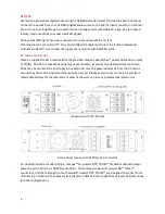
While the ADAPTive systems provide a complete data and power cabling solution, users can consult
the cable and connector information below to develop their own cabling solutions if desired to meet
specific challenges they face in system deployment. It is critical that all components of any user-
provided solution meet these specifications.
Cable:
Ethernet CAT5e UTP or better (300 feet/91 meters maximum)
etherCON™ Connector:
RJ45 with or without Neutrik® NE8MC cable carrier
Multi-Pin Connector:
Link USA™ LK54P (female end on looms, male end on panels)
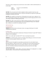
Green Status LED:
A link has been established with another device.
Orange Status LED:
Data is being transferred to/from this port.
Analog Audio
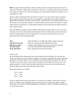
Users wishing to deliver analog audio signal must provide their own XLR cables. The two XLR-type
connectors on the rear of each module, one female and one male, are designed for professional audio
signal levels, nominally 0 dBu (= 0.775 V). Normally, use the female XLR as the signal input. Use the
male XLR as a loop-thru output to connect the same signal input to additional modules.
For correct
system operation, it is critical that all modules within an array or cluster receive an identical input
signal
.
All signal processing is performed within each module.
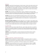
The wiring convention is as follows:
Pin 1: Shield
Pin 2: +/Hot
Pin 3: -/Cold
Once an analog signal has been connected to one module within a system, that module can act as a
Dante™ on-ramp and transmit digital audio data to the rest of the networked modules via Dante™.
Though users may choose to loop analog audio to all modules in an array for additional redundancy, it
is not necessary to do so.
Summary of Contents for ADAPTive systems
Page 1: ...Accessory Rigging Guide...


