background image

4 . 4

E n g i n e e r i n g   D e s i g n

The core acoustical design of the DSA Series dates back to the late 1930s in
Harry Olson’s book,  “Acoustical Engineering”. He showed that, by using
different signal delays on the input to each transducer in a simple line array,
the array’s main output lobe could be effectively “steered”. While this
concept has certainly been used before, the design of the DSA Series goes far
beyond this simple concept.

The engineering design for the DSA Series is certainly capable of “steering”
the main output lobe, as per Olson. However, the shape of the lobe in the
vertical plane is also variable. This allows changing the depth of the
coverage to precisely fit the listening area thereby reducing troublesome
near-to-far SPL differences. 

A major advantage of DSA is the character of its radiation pattern. Contrary to
what might be intuitively assumed, the DSA’s radiation pattern is not the same
as simply down-tilting a loudspeaker that has the same horizontal and vertical
beamwidths. The example EASE plots illustrate this difference.

The radiation pattern of the conventionally, down-tilted loudspeaker has at
least two problems. The geometry of the pattern results in inadequate
coverage across the front area of the room. It also focuses a distinct line of
energy along the side wall. This energy is nearly at the same loudness as the
floor seating area. The sound reflections off the upper part of the wall will
arrive at many listeners late enough to impair intelligibility. These
reflections add to the direct sound and cause the higher intensity sound
seen at the rear , even though these areas are further from the loudspeaker. 

By contrast, the radiation pattern of the DSA loudspeaker is far more consistent
across the entire floor area. The energy it directs to the sidewalls is not only
lower in level, but creates a very different reflection pattern. The sound reflected
off the wall will be largely directed down into the floor or nearby listeners along
the sides, arriving early enough to actually enhance intelligibility.

14

Ver: 30°

Hor: 120°

Lspk: S1
Project: DSAMultipurpose-Tilt
Map: Direct SPL
Freq: 5000 Hz
[Third Octave Average]
Shadow Cast: No
Resolution = 1.0 m

Ver: 30°

Hor: 120°

Lspk: S1
Project: DSAMultipurpose-Steer
Map: Direct SPL
Freq: 5000 Hz
[Third Octave Average]
Shadow Cast: No
Resolution = 1.0 m

Figure 4.4a   Angled Radiation Pattern

Figure 4.4b   DSA Steered Radiation Pattern

Summary of Contents for DSA230

Page 1: ...D S A 2 5 0 D S A 2 3 0 L O U D S P E A K E R O W N E R S M A N U A L ...

Page 2: ...eatures 12 4 2 1 Acoustical 12 4 2 2 Electronic 12 4 2 3 Computer Control 12 4 2 4 Networking 12 4 2 5 Physical 13 4 3 Applications 13 4 4 Engineering Design 14 4 5 DSAPilot 15 4 6 Low Frequency Performance 15 4 7 Comparison To Traditional Products 15 4 8 Designing DSA Systems 16 Chapter 5 Installation 5 1 Electrical Installation 16 5 1 1 Cable Routing Considerations 16 5 1 2 Audio Signal Connecti...

Page 3: ...30 6 1 2 LED Indicator 30 6 1 3 Signal Monitoring 31 6 2 Operational Check List 32 6 3 Normal Operation 32 6 3 1 Powering Up 32 6 3 2 Signal Processing Settings 32 6 3 3 Operation 33 6 4 Operational DOS and DONTS 33 6 4 1 Equalization 33 6 4 2 Maximum Output 33 6 4 3 Low Frequency Content 33 6 4 4 Input Limiting 33 6 4 5 DSAPilot Adjustments 33 Chapter 7 Maintenance and Service 7 1 Warranty 34 7 2...

Page 4: ...y capable of full range music applications With integral signal processing and amplification DSA loudspeakers are economical and simple to use This manual provides information about the design configuration and operation of DSA Series loudspeakers It is intended to be used in conjunction with the DSAPilot Windows based software Please thoroughly familiarize yourself with this manual The more you l...

Page 5: ...dangerous voltage within the product s enclosure that may be of sufficient magnitude to constitute a risk of electric shock to persons The exclamation point within an equilateral triangle is intended to alert the user of the presence of important operating and maintenance servicing instructions in the literature accompanying the appliance This apparatus does not exceed the Class A Class B whicheve...

Page 6: ...ltage rating on the loudspeaker matches the nominal AC Mains voltage being supplied 115 V or 230 V 50 Hz or 60 Hz DANGER DO NOT APPLY 230 V MAINS POWER IF THE VOLTAGE RATING ON THE LOUDSPEAKER IS 115 V IMMEDIATE AND CATASTROPHIC DAMAGE TO THE LOUDSPEAKER WILL RESULT AND MAY CAUSE A FIRE HAZARD SERIOUS PERSONAL INJURY OR DEATH 4 Object and Liquid Entry Take care that objects do not fall into and li...

Page 7: ...amage save the packing materials for the carrier s inspection notify the carrier immediately and file a shipping damage claim Although EAW will help in any way possible it is always the responsibility of the receiving party to file any shipping damage claim The carrier will help prepare and file this claim 2 3 Returning Products to EAW If the loudspeaker must be returned to EAW contact the EAW Ser...

Page 8: ... separately or set up for a priority override function Audio B overrides Audio A Equalization compression and level are separately adjustable for each input Overall signal delay for each loudspeaker cluster is also provided Audio A and B each 2 conductor shielded audio cable supplied Phoenix Contact terminal block plug 3 3 Computer Control Connection NOTE Set the EIA 485 Terminate Switch to ON For...

Page 9: ... the enclosure there is a correct top and bottom This cannot be assumed from the physical appearance Instead orientation depends on application and desired acoustical performance determined using the DSAPilot 2 Ensure the enclosure is oriented correctly by verifying which ends are supposed to be the top and bottom for the intended application The Signal End is the end with the identification LED v...

Page 10: ...Washer through the side of either of the Wall and Enclosure Brackets This prevents the enclosure from being lifted off the Wall Brackets 6 Securely tighten each 3 8 16 Enclosure Bracket Bolt to lock the enclosure at the desired horizontal angle 3 7 Signal Processing The vertical coverage is determined by programming the loudspeaker s digital signal processing Use the DSAPilot to determine the desi...

Page 11: ... SPL in situations with HIGH near to far listener distance ratios User adjustable level control equalization and compression are provided on each of the two audio inputs For situations with multiple locations overall signal delay for each loudspeaker cluster is also provided 4 1 3 PHYSICAL BENEFITS The DSA Series loudspeakers are physically narrow and quite shallow providing a low profile to reduc...

Page 12: ...nd higher outputs at lower frequencies using additional DSA230 s Exceptional intelligibility for reverberant rooms 4 2 2 ELECTRONIC Self powered requiring wiring for AC power line level audio and computer control No amplifier or processing racks needed reducing space and cost Individual amplifier and DSP for each transducer Convection cooled electronics eliminates noisy cooling fans Built in drive...

Page 13: ...eme parks retail spaces and government facilities Its unique capabilities however make it particularly well suited to applications that present a challenging acoustical physical or aesthetic environment The DSA Series is ideal for a variety of venues where achieving good vocal intelligibility is critical These include theatres auditoria houses of worship theme parks retail spaces government facili...

Page 14: ...ilted loudspeaker has at least two problems The geometry of the pattern results in inadequate coverage across the front area of the room It also focuses a distinct line of energy along the side wall This energy is nearly at the same loudness as the floor seating area The sound reflections off the upper part of the wall will arrive at many listeners late enough to impair intelligibility These refle...

Page 15: ... have been applied to the DSA Series to achieve the same high degree of pattern control musicality and ease of setup Though highly complex the DSAPilot s mathematics work behind the scenes Because of this the DSAPilot makes adjusting the signal processing deceptively simple In fact no acoustical knowledge is required to set up and adjust one or multiple DSA Series loudspeakers The only information...

Page 16: ...cabling details may require some variation depending on the particular situation However the basic requirements are the same in all cases Basic electrical installation tasks include Audio signal connection Computer control connection AC mains connection 5 1 1 CABLE ROUTING CONSIDERATIONS The configuration and orientation of the loudspeakers will determine where signal computer and AC mains cabling...

Page 17: ...vailable contact EAW s Application Support Group See Section 7 3 for recommendations about suitable models 3 EIA 485 cabling has special requirements and limitations See Appendix 8 3 for details 5 1 4 DAISY CHAINING COMPUTER AND AUDIO SIGNALS WITHIN CLUSTERS WITH MULTIPLE LOUDSPEAKERS NOTE The Signal Link jacks carry both computer and audio signals The cable between the Signal Link jacks must be w...

Page 18: ...This section provides details about using the optional CobraNet technology for distribution of audio and computer control signals 5 2 1 DESCRIPTION CobraNet is a combination software hardware and network protocol that replaces the audio and computer connections described in Section 5 1 Digitized audio and computer control is distributed by a CAT 5 or better cable to each loudspeaker The network in...

Page 19: ...cable The SECONDARY RJ 45 Ethernet connector on the CM 1 is for connec ting to a second redundant Ethernet network This would be designed as a back up network that automatically takes over in the event of failure in the primary network The digital audio received by the CM 1 connects directly to the loud speaker s digital signal processing It is converted back to analog at the inputs to the interna...

Page 20: ...eutrik PowerCon NAC3MPA AC MAINS jack on the loudspeaker Because of both varying installation and electrical code requirements neither an AC Mains cable nor AC mains supply connection are supplied 1 Supply and connect a 3 conductor power cable to the supplied PowerCon plug ensuring a proper ground connection 2 Supply and attach an appropriate connector for the AC Mains connection at the other end ...

Page 21: ...bleshooting and repair by a qualified service technician Do not attempt further use of the loudspeaker until such repairs are made See Section 8 2 Troubleshooting Fuse Type AGC 0 25 in x 1 25 in slow blow Rating 115 V AC 230 V AC DSA230 4 A 2 A DSA250 8 A 4 A 5 4 Grounding 5 4 1 ELECTRICAL GROUND Ensure that the AC mains grounding conductor in the power cable is properly grounded in accordance wit...

Page 22: ...cally possible to mount a DSA Series loudspeaker either end up Because of the transducer specific signal processing it will NOT provide the desired performance if installed upside down in its intended application CAUTION For DSA Clusters with two or more loudspeakers mounted one over the other it is recommended to make all cable connections before lifting each loudspeaker onto the wall brackets Se...

Page 23: ...here higher LF output capability is desired height restrictions may not permit the ideal over under mounting of the DSA250 and DSA230 models Because of these and other possible requirements the DSAPilot allows several cluster configurations to be used in a single or in multiple locations to achieve various coverage and output results See the DSA Application Guide for details NOTE Where aesthetics ...

Page 24: ... with the LED 5 5 5 ANGLING ENCLOSURES 1 Vertical Angle Normally the DSA Series enclosures are designed to be mounted flat to a vertical surface 2 Horizontal Angle Single Loudspeakers When mounted flat to a vertical surface the mounting hardware allows the enclosures to be rotated up to 15 degrees horizontally 0 being perpendicular to the wall surface This allows directing its fixed 120 horizontal...

Page 25: ... to the equipment injury or death The supplied Wall Brackets are designed for attachment of the loud speaker enclosure to a wall or other vertical surface Ensure both the attachment hardware and the architectural structure are capable of sup porting the load with a design factor that meets applicable building codes Weights DSA230 63 lb 28 6 kg DSA250 90 lb 40 0 kg 1 Using the supplied Wall Bracket...

Page 26: ...attachment hardware and secure the supplied Wall Brackets to the mounting structure complying with all Caution and Warning notes in Section 5 5 1 NOTE The Wall Brackets have a weld nut on one side Be sure to locate this weld nut to the right or left such that the Retainer Bolt can be inserted into the opposite side of the Wall Bracket after the loudspeaker is mounted 26 4 9 in 123 9 mm 5 4 in 136 ...

Page 27: ...recommended that lifting the enclosure in place be performed by at least two people to prevent it from falling during its installation and causing possible equipment damage injury or death CAUTION For DSA Clusters with two or more loudspeakers mounted one over the other it is recommended to make all cable connections before lifting the loudspeakers onto the wall brackets See Sections 5 2 through 5...

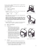
Page 28: ...tainer Bolt does not clamp or support anything It serves only to retain the enclosure on the wall brackets not to lock it into position 2 Route cabling as required using the rear channels in the enclosures extrusion 3 Rotate the enclosure to the desired horizontal angle Firmly tighten each Enclosure Bracket Bolt to secure the enclosure in the desired position 28 1 4 20 X 3 LG HEX HEAD SCREW LOCK W...

Page 29: ...Installation Adjustment of the signal processing and thus the acoustical performance for each DSA Cluster is accomplished using the DSAPilot program Complete instructions for its use can be found in the DSAPilot Help file These are the basic tasks that need to be done using the DSAPilot 1 Select each cluster configuration used in the system design 2 Assign the installed clusters to those selected ...

Page 30: ... saving function that improves energy efficiency This feature automatically puts the DSA amplifiers into stand by mode similar to a computer monitor The initiation of this mode occurs after the input signal is absent for a period of time Enable or disable this function using DSAPilot If enabled the period of time the input signal must be absent before entering stand by is adjustable In addition DS...

Page 31: ...disable this indication to avoid the audience seeing flashing LEDs particularly on dynamic program In this case determine the source level that triggers the Output Compressor Limiters Monitor and control the source level so as not to exceed this pre determined trigger level This will help prevent the DSA Output Compressor Limiters from activating more than occasionally 4 System Error If this indic...

Page 32: ...an desired output SPLs 6 3 Normal Operation 6 3 1 POWERING UP Power is applied to DSA in one of three ways 1 Always On Connect the loudspeaker to a continuously powered AC mains supply The loudspeaker is always ready for use For this mode disable the Power Management function 2 Off On Connect the loudspeaker to an AC mains supply which is switched on and off between uses The AC mains must be switc...

Page 33: ...te clipping at most once every few seconds 6 4 3 FREQUENCY CONTENT Do not attempt to boost low frequencies below about 100 Hz The 4 in drivers DSA loudspeaker are not designed to replace subwoofers if strong very low frequency response is needed Boosts below 100 Hz can greatly increase the cone excursion and can use up much of the amplifier power available These conditions can significantly reduce...

Page 34: ...tions about configuring or operating the loudspeakers contact EAW Application Support Group Tel 508 234 6158 Tel 800 992 5013 USA only Fax 508 234 8251 e mail asg eaw com 7 3 2 SERVICE INFORMATION For questions about troubleshooting or servicing a DSA Series loudspeaker contact Mail EAW Service Department One Main Street Whitinsville MA 01588 USA Tel 800 992 6001 USA only Tel 508 234 6001 Fax 508 ...

Page 35: ...on about the integrity or capability of any mounting or rigging part to perform its intended function it must be immediately removed from service for repair or replacement 8 1 2 PERFORMANCE TESTING Listening tests and or formal measurements should be done periodically The interval between such tests will depend on the frequency of system usage and the conditions of use All transducers should be te...

Page 36: ...r needs service or more drivers No output Incorrect connections Check that input cabling to the loudspeaker is wired correctly for the signal wires and cable shield No output Loudspeaker is off Check that power is supplied to the loudspeaker power cable and that the cable is connected to the loudspeaker No output Loudspeaker is off Check the fuse on the power end of the loudspeaker Replace if blow...

Page 37: ...thest end of the EIA 485 cable run All other Terminate Switches should be OFF No computer communication Loudspeaker is powered off Ensure the loudspeaker is powered on No computer communication or Improper network Ensure the EIA 485 cabling and only with some loudspeakers configuration termination conforms to the notes in Section 8 3 No computer communication Improper link connections Ensure the E...

Page 38: ...485 claims maximum cable lengths of 4 000 ft However the fastest data rates for a DSA network assuming ideal network conditions limit the maximum to 2 800 ft 850 m Performance variations for the network cable connectors EIA 485 drivers and several other variables can and often do further reduce this length Therefore this is the maximum recommended length to ensure reliable communications 5 DO use ...

Page 39: ...rs using the Signal Link connectors Therefore use the Terminate Switch only on the loudspeaker within a cluster that is connected to the network via the Phoenix connector 8 4 Support For Ethernet The infrastructure for a CobraNet network must be designed and built using standard IEEE 802 3u 100BASE T Ethernet network hardware As this is a standardized technology EAW does not provide technical supp...

Page 40: ...0 36 51 23 89 DIMENSIONS APPLY TO BOTH SIDES RIGHT SIDE INPUT PANEL POWER END FRONT GRILLE PARTIALLY SHOWN DSA230 EASTERN ACOUSTIC WORKS 4 36 BACK 2X 14 11 24 2X 20 FROM WALL LED INPUT PANEL 9 34 9 32 SIGNAL END 8 26 CABINET WEIGHT 62 LBS 40 ...

Page 41: ... APPLY TO BOTH SIDES RIGHT SIDE INPUT PANEL POWER END GRILLE PARTIALLY SHOWN GRILLE PARTIALLY SHOWN FRONT DSA250 EASTERN ACOUSTIC WORKS 4 36 BACK 2X 14 2X 20 INPUT PANEL 9 32 9 34 LED 11 24 FROM WALL SIGNAL END 8 26 CABINET WEIGHT 84 LBS 41 ...

Page 42: ...62 in 15 8 mm 4 00 in 101 5 mm 4X Ø 0 38 in 9 65 mm FIGURE 9 3 WALL BRACKET FULL SCALE See Section 5 5 7 for Mounting Instructions 3 0 inch standard 76 2 mm Verify this dimension before using this template When printing this PDF template make sure to deselect Fit to page option 9 3 WALL BRACKET 42 ...

Page 43: ......

Page 44: ...One Main Street Whitinsville MA 01588 508 234 6158 FAX 508 234 8251 Par t No RD0086 B 27AUG03 ...

Reviews: