background image

25

8 . 5    

A m p l i f i e r   S e r v i c e

WARNING:

Disconnect the ac mains cable before doing this procedure.

ATTENTION:

Déconnectez le cordon du secteur avant d'entamer cette procédure.

ATTENZIONE:

Prima di procedere con questa operazione, disconnettere il cavo

d'alimentazione AC.

PRECAUCION:

Desconecte el cable de alimentación antes de realizar este proceso.

WARNUNG:

Ziehen Sie den Netzstecker aus der Steckdose, bevor Sie mit dieser Prozedur beginnen.

Faulty electronics are serviced by replacing the entire amplifier module.

8 . 5 . 1

A m p l i f i e r   M o d u l e s

There are two types of NT amplifier modules: 
one for the NT full-range models and one for the subwoofer.

1. Full-range: Input, DSP, 1000 W @ 4 ohm LF amplifier, 500 W @ 4 ohm 

HF amplifier, and power supply.

2. Subwoofer: Input, DSP, two 1000 W @ 4 ohm amplifiers, and power supply.

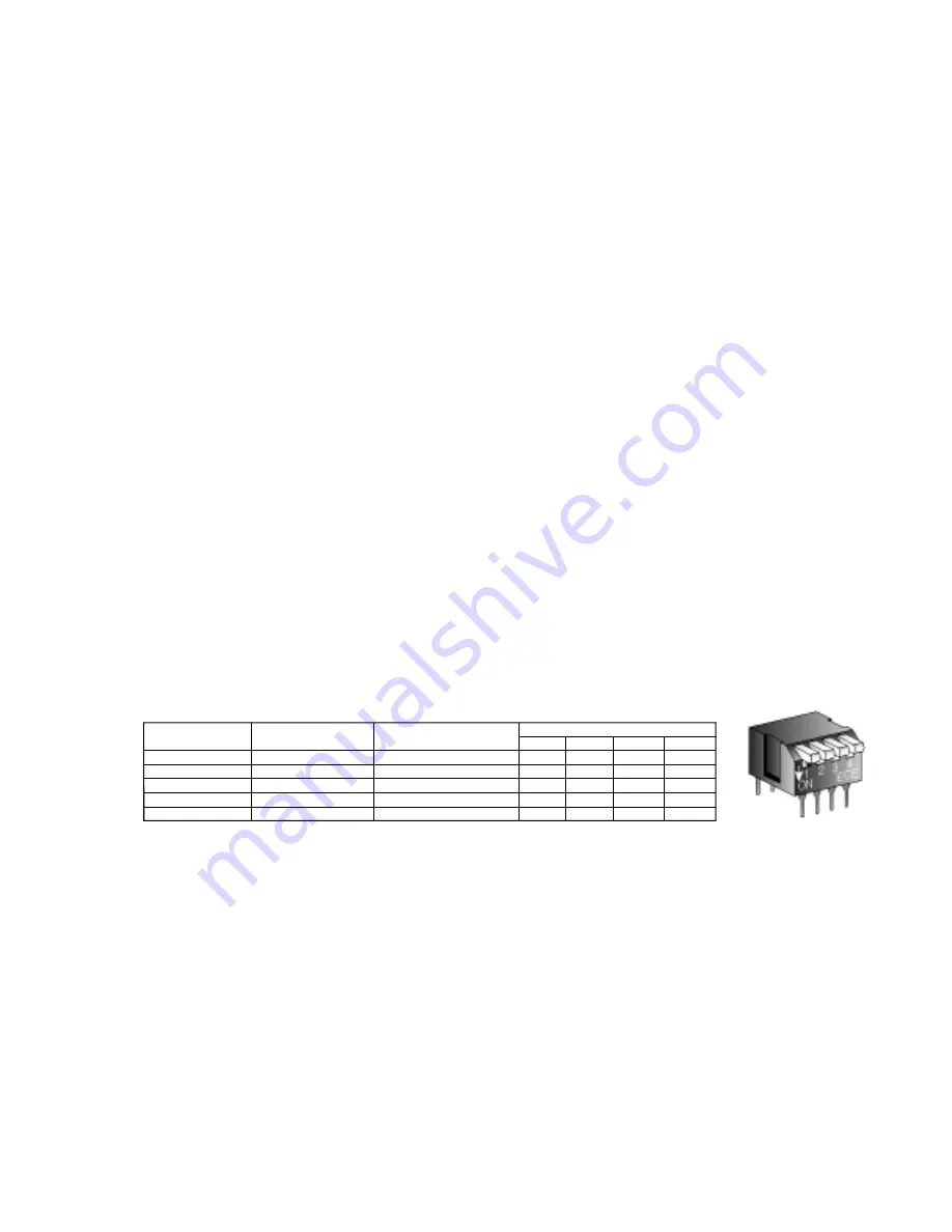
For the NT full-range models (NT2x & NT5x), each amplifier module has the DSP settings
for all models stored in on-board memory. The active settings are determined by on-board
dip switch settings. Thus,amplifier modules for the full-range models are interchangeable 
by simply resetting the dip switches for that particular model.

8 . 5 . 2  

N T   A m p l i f i e r   R e p l a c e m e n t   M o d u l e s   a n d   D i p   S w i t c h   S e t t i n g s

An amplifier replacement module consists of the power amplifiers, DSP board, power
supply, connectors, and indicators; all pre-mounted on the amplifier panel.

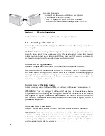
Amplifier Module Replacement Part Numbers & Dip Switch Settings

NOTE

: If the incorrect DIP switch position is used, poor/incorrect performance will result,

at best sounding bad, at worst causing equipment failure.

8 . 5 . 3

R e p l a c i n g   t h e   A m p l i f i e r   M o d u l e

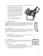
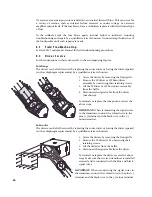
1. Remove the amplifier module from the other side of the enclosure by removing its12

retaining screws.

2. Disconnect the quick release connector for the transducer cabling.

3. Configure the replacement amplifier for the NT model by setting the dip switch. See

the chart in Section 8.5.2 for the correct settings. The dip switch is located behind the
input receptacles on the backside of the amplifier module.

4. Once the dip switch is programmed, connect the transducer cabling to the 

replacement module.

NT Model #

115 V Module

NT26
NT29
NT56
NT59
NTS22

#0016088
#0016088
#0016088
#0016088
#0016090

230 V Module

Dip Switch Settings

#0016584
#0016584
#0016584
#0016584
#0016585

Off
Off
Off
Off
Off

Off
Off
Off
Off
On

Off

On

On

Off

Off

Off
On
Off
On
Off

1

2

3

4

NOTE:  Off is up, On is down.

Summary of Contents for NT29

Page 1: ...N T S E R I E S O W N E R S M A N U A L F U L L R A N G E A N D S U B W O O F E R L O U D S P E A K E R S ...

Page 2: ...rises secteur de votre région faites appel à un électricien agéé pour modifier le cordon secteur en fonction du format local Vérifiez que la fiche secteur dispose d une mise à la terre Le non respect de la mise à la terre peut entraîner des dommages aux équipements et des accidents aux personnes pouvant être fatal 1 Precauzioni di Sicurezza Da Leggere per Primo 1 1 Norme di Sicurezza Prima di proc...

Page 3: ...ker ausgeliefert Sollte der Netzstecker nicht in Ihre Netzsteckdose passen dann lassen Sie von einem zugelassenen Elektrobetrieb einen passenden Netzstecker montieren Stellen ie sicher dass der Schutzkontakt der Netzsteckdose einen guten Kontakt zur Erde hat Nichtbeachtung dieser Hinweise können möglicherweise zu Schäden am Equipment oder zu Verletzungen bzw zum Tod von Personen führen 1 2 EC Decl...

Page 4: ...ad Limits 9 5 2 Application Configurations 9 5 2 1 Full Range Loudspeaker 9 5 2 2 Subwoofer 10 5 2 3 Stage Monitor 10 5 2 4 Moving the Amplifier Module 10 5 3 Configuring Arrays 11 5 3 1 Center of Gravity 11 5 3 2 Vertical Array 11 5 3 3 Horizontal Array 11 Section 6 Electrical Installation 6 1 Audio Signal Connection 12 6 1 1 Input Panel 13 6 1 2 Loop Connector 13 6 2 System Gain 13 6 2 1 Level C...

Page 5: ...7 4 Signal Processing 20 7 4 1 Internal Signal Processing 20 7 4 2 External Signal Processing 20 7 4 3 Limiters 20 Section 8 Maintenance and Service 8 1 Maintenance 21 8 2 General Service 21 8 2 1 AC Mains Fuse 21 8 3 Field Troubleshooting 24 8 4 Driver Service 24 8 5 Amplifier Service 25 8 5 1 Amplifier Modules 25 8 5 2 NT Amplifier Replacement Modules and Dip Switch Settings 25 8 5 3 Replacing t...

Page 6: ...10 Hz Mode Normal Subwoofer Gain 0 dB Polarity Normal WARNING Before connecting an NT loudspeaker to the ac mains supply completely turn down the input signal to the loudspeaker using the signal source s output level master volume control or other output level control If not there could be excessive and possibly damaging sound levels from the loudspeaker when energized 3 2 Audio Connection Connect...

Page 7: ...Initiaux Utiliez ces réglages de face arrière Large bande sans Subwoofer HPF 55 Hz Mode Normal Large bande avec Subwoofer HPF 110 Hz Mode Normal Subwoofer Gain 0 dB Polarité Normale ATTENTION Avant de connecter une enceinte NT au secteur coupez le signal rrivant en entrée de l enceinte en réglant le niveau de sortie de la source au minimum réglage de niveau général Master ou tout autre réglage de ...

Page 8: ...rimento alle figure 3 1 Imposazioni Iniziali dei Controlli Usa queste regolazioni nominali per gli switches del pannello posteriore Full Range senza subwoofer HPF 55 Hz Mode Normal Full Range con subwoofer HPF 110 Hz Mode Normal Subwoofer Gain 0 dB Polarity Normal ATTENZIOE Prima di collegare il diffusore NT alla presa di alimentazione abbassa completamente il livello del segnale in ingresso agend...

Page 9: ... Inicio Rapido Si quiere empezar a usar la unidad inmediatamente o si ya tiene un cierto conocimiento acerca del uso de altavoces autoamplificados en estas instrucciones de Inicio Rápido encontrará los detalles relativos a estos altavoces N Series Para comprender las instrucciones de esta sección consulte las figuras que se acompañan 3 1 Ajustes de Control Iniciales Utilice estos ajustes nominales...

Page 10: ...l hacer esto evitará la entrada de niveles de sonido excesivos y posiblemente dañinos al altavo 3 Schnellanletung Falls Sie sich in Eile befinden oder bereits mit der Nutzung aktiver Lautsprecher vertraut sind können Sie dieser Schnellanleitung produktspezifische Details zu den Lautsprechern der NT Serie entnehmen Für die Anweisungen in diese Kapitel finden Sie entsprechende Abbildungen 3 1 Anfang...

Page 11: ...ou fully understand proper installation and operation before use 4 1 Using the Loudspeaker You will need to perform the following general tasks to properly put the loudspeaker into service The details for each task are provided in this manual 1 Design and install a rigging or mounting system to support the loudspeaker in its intended location and aimed in the desired direction 2 Connect a line lev...

Page 12: ...etries The result is significantly reduced distortion NT Models 4 2 2 Amplification As is true of all professional loudspeaker systems the performance of the NT Series loudspeakers depends on amplifiers delivering an adequate supply of clean power To maximize performance the full range loudspeakers are bi amplified meaning the LF and HF drivers each have their own signal processing and built in hi...

Page 13: ...ng Rigging WARNUNG Lesen und beachten Sie alle Warnungen und Sicherheitshinweise in der mitgelieferten EAW Lautsprecher Bedienungsanleitung bevor Sie das Produkt benutzen Nichtbeachtung dieser Hinweise können möglicherweise zu Schäden am quipment oder zu Verletzungen bzw zum Tod von Personen führen 5 1 1 Mounting Point Working Load Limits Enclosure Oriented Horizontally NT s integral mounting poin...

Page 14: ...gulations 5 2 3 Stage Monitor As a stage monitor the NT full range loudspeaker is designed to lay on one of its angled sides on the floor The enclosure s trapezoidal shape provides an ideal angle for aiming up toward performers from a stage floor Because of the enclosure s symmetrical shape you can place the loudspeakers in a matched left right pair with both HF horns inward or outward with respec...

Page 15: ... assistance in configuring NT arrays contact EAW s Application Support Group 5 3 1 Center of Gravity It might seem intuitive that for the NT full range models the side of the enclosure with the amplifier would be heavier However the center of gravity for all models is on the left to right centerline Thus when suspending NT loudspeakers there is no weight or balance advantage to moving an amplifier...

Page 16: ...de niveau général Master ou tout autre réglage de niveau de sortie Dans le cas contraire le niveau sonore risque d être excessif ce qui peut causer des ésions auditives irréversibles lors de la mise sous tension de l enceinte Conneccione del Segnale Audio Collega il segnale audio al diffusore PRIMA di collegare il diffusore all alimentazione AC ATTENZIONE Prima di collegare il diffusore NT alla pr...

Page 17: ... to multiple NT loudspeakers and NT subwoofers Because the signal processing including the crossover is built in full range loudspeakers and subwoofers may be daisy chained together from a single signal source NOTE To avoid potential interference do not leave an un terminated cable attached to either the Input or the Loop connector 6 2 System GAIN 6 2 1 Level Control The electronic sensitivity and...

Page 18: ...D INCENDIE DE BLESSURES GRAVES VOIRE FATALES Alimentazione AC ATTENZIONE Leggere tutte le istruzioni e le avvertene riguardanti l alimentazione elettrica incluse nel Manuale EAW Loudspeaker PERICOLO Assicurarsi che il voltaggio dell alimentazione utilizzata nell area in cui si intende utilizzare il diffusore corrisponda al voltaggio riportato nel pannello posterore del diffusore vicino alla connes...

Page 19: ...he Neutrik PowerCon NAC3FCA adatée à l embase secteur Neutrik PowerCon NAC3MPA de l enceinte ATTENTION Il se peut que le format de la fiche secteur ne corresponde pas à celui de votre situation géographique Dans ce cas faites appel à un électricien agréé pour qu il remplace la fche par une autre du bon format Respectez les normes électriques de câblage locales ATTENTION Assurez vous que la ligne s...

Page 20: ... Verbindung zur Erde hat Nichtbeachtung dieses Hinweises kann zu Schäden am Equipment zu Verletzungen oder zum Tod führen Power Cable Color Coding NOTE If an extension cord is used for the ac mains use only a cord rated for at least 1800 VA 6 3 3 Power On Off CAUTION There is no power switch on the loudspeaker When connected to the ac mains the loudspeaker will be energized and fully operational w...

Page 21: ...tion of music and speech With Subwoofer Not recommended This will cause excessive energy between 55 Hz and 110 Hz 110 Hz switch to right With Subwoofer Provides normal acoustic integration with a subwoofer Without a Subwoofer Recommended for speech only not recommended for music 6 4 2 Setting the Operating Mode The Mode switch sets the voicing of the loudspeaker for different applications It compe...

Page 22: ...control This is normally accomplished using separate auxiliary or matrix outputs on a mixing console 2 Provide an external attenuator to the loudspeaker that needs less gain This can be a fixed resistive attenuator ideal for permanent installations Where frequent adjustment may be needed such as in a portable system an adjustable level control may be inserted into the signal line to the loudspeake...

Page 23: ...ly meaning no more than once every 3 seconds or so then levels are probably OK but at maximum If this indicator is flashing more than once every 3 seconds or so reduce the input signal level 7 3 2 Clip A Clip indicator on the rear panel illuminates if any of NT s electronics are being driven into clipping This includes the entire signal chain from the input stage through the DSP Clipped signals ca...

Page 24: ...t results in a variety of venues The processing was determined from extensive laboratory measurements and field testing to provide the maximum performance in terms of frequency response phase response power handling and audio quality It affects many aspects of the loudspeaker s performance including frequency response beamwidth consistency output level capability and wavefront coherency 7 4 2 Exte...

Page 25: ...ipo de mantenimiento o reparación Service WARNUNG Ziehen Sie das Netzkabel aus der Steckdose evor an der Box gearbeitet wird Certain NT loudspeaker components are field replaceable These include the drivers and amplifier module All other service and repair information must be obtained by contacting the EAW Service Department or the service department of the EAW Distributor for your country See the...

Page 26: ...180 A2s T temporisation fusion lente H haute rupture 1500 A Revendeur Wickmann pièce référence 181 2100 002 par 10 Modèles en 230 Vca T6 3A H 125 V I2t 110 A2s T temporisation fusion lente H haute rupture 1500 A Revendeur Wickmann pièce référence 181 1630 002 par 10 Fusibile AC CAUTELA Per essere conformi alle certificazioni di sicurezza approvate utilizzare fusibili che soddisfino le specifiche r...

Page 27: ...002 cantidad mínima 10 modelos de 230 V T6 3A H 125 V I2t 110 A2s T retardo ruptura lenta H corriente elevada 1500 A Distribuidor Wickmann nº referencia 181 1630 002 cantidad mínima 10 Netzsicherung VORSICHT Um die Sicherheitsbestimmungen zu erfüllen verwenden Sie ausschließlich Sicherungen ie die korrekte Charakteristik Spitzenstrombelastbarkeit und Auslösezeit I2t A2s sowie Auslösestrom besitzen...

Page 28: ...e 2 Remove the LF driver or HF horn driver assembly by unscrewing their retaining screws 3 Lift the LF driver or HF horn driver assembly from the baffle 4 Disconnect the signal cable from the driver not shown To reinstall or replace the component reverse the above steps IMPORTANT When reconnecting the signal wires to the transducer connect the colored wire to the plus terminal and the black wire t...

Page 29: ...the dip switches for that particular model 8 5 2 NT Amplifier Replacement Modules and Dip Switch Settings An amplifier replacement module consists of the power amplifiers DSP board power supply connectors and indicators all pre mounted on the amplifier panel Amplifier Module Replacement Part Numbers Dip Switch Settings NOTE If the incorrect DIP switch position is used poor incorrect performance wi...

Page 30: ... lines Alternately the full range input can be connected to the subwoofer and looped through to the full range loudspeaker dotted lines AMP LF AMP LF EQ DELAY LPF LIMIT DSP PC BOARD INPUT A D IN THRU D A AMPLIFIER POWER SUPPLY ASS Y 1000 W 4 OHM 1000 W 4 OHM NT SUBWOOFER AMP HF AMP LF HPF EQ LIMIT DELAY DSP PC BOARD INPUT A D IN THRU D A D A AMPLIFIER POWER SUPPLY ASS Y 500 W 4 OHM 1000 W 4 OHM LP...

Page 31: ...27 ...

Page 32: ... 234 6158 fax 508 234 8251 web www eaw com T h e L a w s o f P h y s i c s T h e A r t o f L i s t e n i n g EAW is the worldwide technological and market leader in the design and manufacture of high performance professional loudspeaker systems RD0385 D JAN06 ...

Reviews: