background image

7.5.5

LISTE

N

ER DISTA

N

CE A

N

D AIR LOSS PRE-EMPHASIS

IMPORTANT !!

In order for the Air Loss Pre-emphasis to be effective, the ambient temperature and
humidity values MUST be manually entered using the UTIL menu on the UX8800's

front panel. (See Sections 5.3.4 and 5.3.5.)

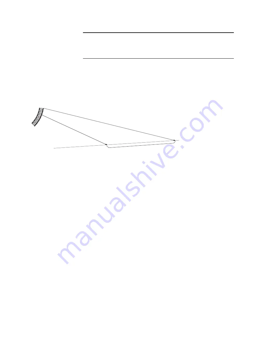
If enabled, scroll through and set the Listener Distance (1 m to 256 m) from the array to the closest part of
the audience area covered by the portion of the array to which the pre-emphasis is applied. 

The Listener Distance is a parameter of the Air Loss Pre-emphasis filter that compensates for high
frequency air loss over distance. The parameters of this filter are calculated from the user-entered ambient
temperature, relative humidity, and listener distance. 

While only a single distance is entered for the Air Loss Pre-Emphasis Filter, the audience covered by a

given portion of an array or loudspeaker will vary in distance from the array. The

recommendation for setting the distance to the closest listeners in this area

is because there is far lower listener tolerance for excessive

brightness than a lack of brightness. Thus, if the

distance is set for the closest part of the

audience area covered by the filtered

portion of the array or loudspeaker,

then the more distant listener will

hear less bright sound. However, if

the distance is set for audience further

back in this area, then the sound for the closer

listeners in this area will be excessively bright and likely annoying. In any case, you can adjust the
brightness to taste by adjusting the distance parameter.

NOTE: 

To bypass

the Air-Loss Pre-emphasis 

filter: s

et the 

Listening Dist

to 1 m.

7 . 6

L E V E L   ( I n p u t   C h a n n e l s   A   t o   D )

Use the LEVEL function to set Input Channel gain and polarity by selecting the A to D buttons.

Level:

Scroll through and select the gain up to +/- 15 dB in 0.1 dB steps.

Polarity:

Select the polarity: + or  -.

7 . 7

X - OV E R   ( I n p u t   C h a n n e l s   A   t o   D )

7.7.1

HPF FREQ A

N

D LPF FREQ

X-Over HPF (if enabled): scroll through and select the frequency. The range will depend on the

particular loudspeaker model. This setting affects the entire loudspeaker.

X-Over LPF (if enabled): scroll through and select the frequency. The range will depend on the

particular loudspeaker model. This setting affects the entire loudspeaker.

The X-Over HPF and LPF filters are typically used in either of two ways. 

1. Stand-alone Loudspeakers and Arrays:

For full-range loudspeakers and subwoofers, the LF subsystem has an HPF enabled that
is set to protect the loudspeaker from excessive LF signals that are below its operating
range. Normally, leave HPF settings at their default values. This is always a 12 dB per
octave Butterworth filter.

For applications such as voice-only, fill usage, and similar, set a higher frequency HPF
to restrict unwanted low frequency signals. This automatically changes the HPF filter
from its normal 12 dB per octave Butterworth filter to a more appropriate filter, most
commonly a 24 dB per octave Linkwitz-Riley filter.

For subwoofers an adjustable LPF, 24 dB per octave, Linkwitz-Riley is enabled for their
low-pass crossover filter.

Page 18

AUDIENCE AREA

 COVERED BY

 PORTION OF THE 

ARRAY OR

LOUDSPEAKER WI

TH AIR LOSS PRE-EM

PHASIS APPLIED

INITIALL

Y, SET

 THE LISTENER

DIST

ANCE T

O THIS 

DIST

ANCE 

Summary of Contents for UX8800

Page 1: ...12 12 Sig Sig Clip Clip Lim Lim 12 12 Sig Sig Clip Clip Lim Lim 12 12 Sig Sig Clip Clip Lim Lim 12 12 Sig Sig Clip Clip 6 6 12 12 Sig Sig Clip Clip 6 6 12 12 Sig Sig Clip Clip 6 6 12 12 Sig Sig Clip C...

Page 2: ...Page ii...

Page 3: ...must remain accessible to be able to disconnect power from the apparatus 11 Protect the power cord from being walked on or pinched particularly at plugs convenience receptacles and the point where th...

Page 4: ...quilat ral pr vient l utilisateur de la r sence d instructions importantes relatives l utilisation et la maintenance du produit dans le manuel fourni avec le produit 1 Lisez ces instructions 2 Conserv...

Page 5: ...longue avantde causer de tels dommages vitez toute exposition prolong e aux niveaux sonores lev s DANGER Danger d explosion en cas de non remplacement correct de la pile Remplacez uniquement par une...

Page 6: ...alla pioggia l unit non funziona correttamete oppure caduta 16 Non esporre questa unit a gocce o schizzi di alcun liquido Non posizionare sull unit oggetti contenenti liquido come vasi o bicchieri 17...

Page 7: ...aja en su salida de corriente p ngase en contacto con un electricista ara que sustituya esa salida obsoleta 10 El enchufe de salida de corriente debe quedar accesible para que pueda desconectar el cab...

Page 8: ...htung dieser Hinweise k nnen m glicherweise zu Sch den am Equipment oder zu Verletzungen bzw zum Tod von Personen f hren Sollte es Widerspr che oder berlappungen geben mit anderen Produktanleitungen g...

Page 9: ...ose mit drittem Schutzleiterkontakt 18 Dieses Ger t erf llt die Class A Class B Richtlinien je nachdem elche zutrifft in Bezug auf die Aussendung von St rstrahlung die von digitalen Ger ten ausgehen w...

Page 10: ...Immunity The Technical Report File is maintained at LOUD Technologies Inc Worldwide Headquarters 16220 Wood Red Road NE Woodinville WA98072 USA Tel 1 425 892 6500 Tel 866 858 5832 Fax 1 425 487 4337...

Page 11: ...ons 6 5 OPERATION INITIAL SETUP 9 5 1 Power On Off 9 5 2 Front Panel Controls 9 5 3 UTIL System Set Up 10 6 OPERATION SYSTEM PROCESSOR MODE 12 6 1 Introduction 12 6 2 Select System Processor Mode 12 6...

Page 12: ...ing Damage If you find the processor is damaged after unpacking save the packing materials for the carrier s inspection notify the carrier immediately and file a shipping damage claim Although EAW wil...

Page 13: ...hile providing robust driver protection These preset parameters are locked down to prevent inadvertent or purposeful modifications However the user retains control of gain input EQ signal delay and po...

Page 14: ...240 V 50 Hz to 60 Hz 13 ac mains fuse 4 A slow blow main and spare in IEC Receptacle drawer 14 Power ac mains on and off 15 Outputs 1 to 8 XLR connectors for audio outputs analog 16 Inputs A to D XLR...

Page 15: ...in compliance ratings keep the ac mains voltage between 100 V to 240 V 4 2 2 IEC POWER CORD RECEPTACLE An IEC 320 ac mains inlet on the rear panel accepts the detachable power cords supplied with the...

Page 16: ...el 2 4 3 3 OUTPUT CONNECTIONS The eight male XLR type connectors labeled 1 through 8 are the audio output connectors Analog XLR 1 to XLR 8 Electronically balanced line level Pin 1 shield Pin 2 plus or...

Page 17: ...cable is required when connecting two Ethernet ports in the same layer of the OSI model Open Systems Interconnection Reference Model A computer s Ethernet port meaning its NIC network interface card a...

Page 18: ...me U Net cables by assigning Input Channel and Output Channel signals to U Net channels 4 4 8 SOFTWARE INSTALLATION EAWPILOT EAWPilot requires an IBM compatible PC equipped as follows Operating System...

Page 19: ...ont panel The display can be adjusted for best viewing using the UTIL LCD Contrast function 5 2 2 FUNCTION BUTTONS Use the function buttons to display and edit the operating parameters of the UX8800 C...

Page 20: ...cessor modes all settings will be reset to the factory default settings for that mode In order to avoid losing any custom settings save them using the PROG function before switching modes During the m...

Page 21: ...col server Static Manually enter an IP address normally a private IP address The first three number groups in the IP address must be the same for both the computer and the UX8800 For example 192 168 0...

Page 22: ...h output channel 6 5 1 6 4 CH Input Channels A to D Use the CH function to set the parameters for Input ChannelsAto D by selecting theAto D buttons 6 4 1 SRC SOURCE 1 SOURCE 2 Select either a single s...

Page 23: ...ressor limiter parameters Lim Sets the Comp Lim to In active or Out inactive Thrsh Scroll through and select the limiter threshold from 20 dBu to 10 dBu in 0 1 dB steps Ratio Scroll through and select...

Page 24: ...find a destination to save the current processing parameters Name the program to be saved If a memory with an existing program is chosen rename the program to be saved This will replace the existing...

Page 25: ...iver time alignment polarity gain crossover filters and high low pass filters These settings are fixed at the factory 2 Gunness Focusing This consists of a precise and highly complex filter specifical...

Page 26: ...s fully user adjustable When set for generic processing the Input Channel processing can be adjusted using the UX8800 front panel However Output Channel processing can only be adjusted using EAWPilot...

Page 27: ...r or array may be voiced incorrectly be over protected or be under protected 7 5 3 AMP GAIN Scroll through and select the Amp Gain for the amplifier connected to that output channel The range is from...

Page 28: ...djusting the distance parameter NOTE To bypass theAir Loss Pre emphasis filter set the Listening Dist to 1 m 7 6 LEVEL Input Channels A to D Use the LEVELfunction to set Input Channel gain and polarit...

Page 29: ...frequency for each filter Variable from 20 Hz to 20 kHz in 1 24th octave steps Gain Scroll through and select the gain for each filter 15 dB in 0 1 dB steps Filt Sets the selected filter 1 to 10 to I...

Page 30: ...put meter make up two different meters 8 4 1 SIG 12 AND CLIP SIG SEGMENTS These three segments monitor the signal level in dB below 0 dBFS 0 dB Full Scale the clip level of the DAC digital to analog c...

Page 31: ...so that any changes will affect all such linked parameters 9 1 3 FIRMWARE UPDATE EITHER MODE Using the Settings tab in the UX8800 interface window the firmware program for the UX8800 can be updated 9...

Page 32: ...onditions that subject the unit to mechanical stress such as part of a portable or touring system 10 2 Service There are no user serviceable parts inside the UX8800 processor In case of failure refer...

Page 33: ...ted The meters function independently of the mute switch No output and no output meter lights on some or all channels Incorrect configuration Check that the output s is assigned an Input Channel Signa...

Page 34: ...Polarity Gain Polarity Meter Meter Meter Meter Meter Meter Meter Meter Meter Meter Meter Meter Limiter Limiter Limiter Limiter Limiter Limiter Limiter Limiter Mute Mute Mute Mute Mute Mute Mute Mute U...

Page 35: ...E MUTE MUTE MUTE MUTE MUTE Preset Gunness Focusing Loudspeaker Processing Sub system Crossover EQ Gain Polarity Limiter Alignment Delay Air Loss Pre emphasis Preset Gunness Focusing Loudspeaker Proces...

Page 36: ...s However the processing algorithms used in the UX8800 differ from the normal textbook algorithms used in digital processors EAWdeveloped new algorithms specifically tailored for digital audio process...

Page 37: ...Page 27...

Page 38: ...Page 28...

Page 39: ...Page 29...

Page 40: ...One Main Street Whitinsville MA USA 01588 508 342 6158 FAX 508 234 8251 Part No 0018676 00 A00 June 2007 Loud Technologies Inc 2007...

Reviews: