8
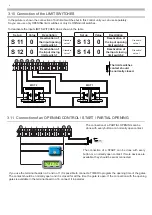
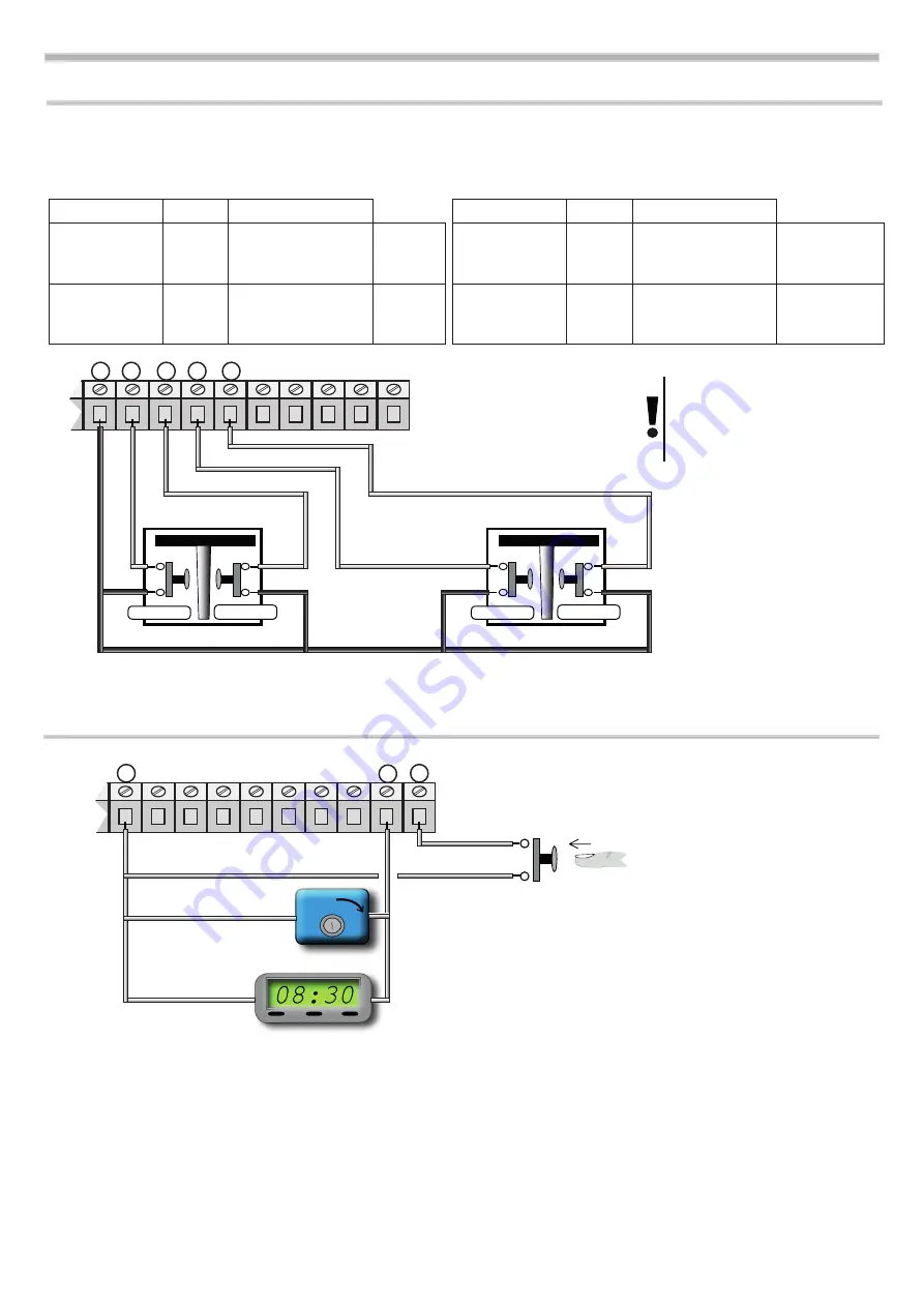
3.10 Connection of the LIMIT SWITCHES
In the picture is shown the connection of both limit switches but in this control unit you can use separately.
So you can use only OPENING limit switches or only CLOSING limit switches.
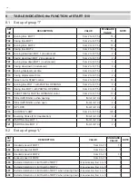
Set up
Value
Description
S 11 0
Deactivation of
the input opening
limit switch 1
Standard
value 1
S 12
0
Deactivation of
the input closing
limit switch 1
Standard
value 1
3 4 5 6 7 8 9 10 11 12
mOT 2
MOT 1
CLOSE
OPEN
CLOSE
OPEN
The limit switches
contact should
be normally closed.
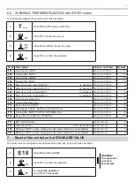
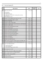
To deactivate the input LIMIT SWITCHES do as shown in the table
Set up
Value
Description
S 13 0
Deactivation of
the input opening
limit switch 2
Standard
value 1
S 14
0
Deactivation of
the input closing
limit switch 2
Standard
value 1
3.11 Connection of an OPENING CONTROL / START / PARTIAL OPENING
3 4 5 6 7 8 9 10 11 12
The connection of a START can be done with every
button or a normally open contact. If more devices are
available, they should be serial connected.
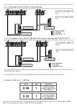
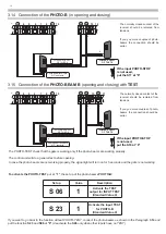
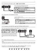
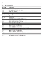
If you use the terminal boards no.3 and no.11 it is possible to connect a TIMER to program the opening time of the gates.
The contact should be normally open and it is closed for all the time the gate is open. If the connection with the opening
gates is available in the terminal board no.16, connect it in parallel.
The connection of a PARTIAL OPENING can be
done with every button or a normally open contact.
Summary of Contents for START S10
Page 21: ...NOTE 21 ...
Page 22: ...NOTE 22 ...
Page 45: ...NOTE 21 ...
Page 46: ...NOTE 22 ...
Page 67: ...NOTE 19 ...
Page 89: ...NOTE 21 ...
Page 90: ...NOTE 22 ...
Page 113: ...NOTE 21 ...
Page 114: ...NOTE 22 ...

