11
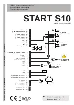
3.19 Check of the connections
Check:
The tension in the terminal board , if all led are turned on (Normally closed), check all securities, right direction of the gate
(it opens first). When the control unit is powered, the L.E.D. (inputs) are turned on when in the input the contact is closed.
The
red l.e.d.
in the inputs
CLS2 - OLS2 - CLS1 - OLS1 - PHOTOA - PHOTOB - STOP
are always
lit on.
The
green l.e.d.
in the inputs
START / PARTIAL OPENING
are always
turned off.
CLS2 OLS2
CLS1 OLS1 PHOTOA PHOTOB STOP START PED
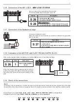
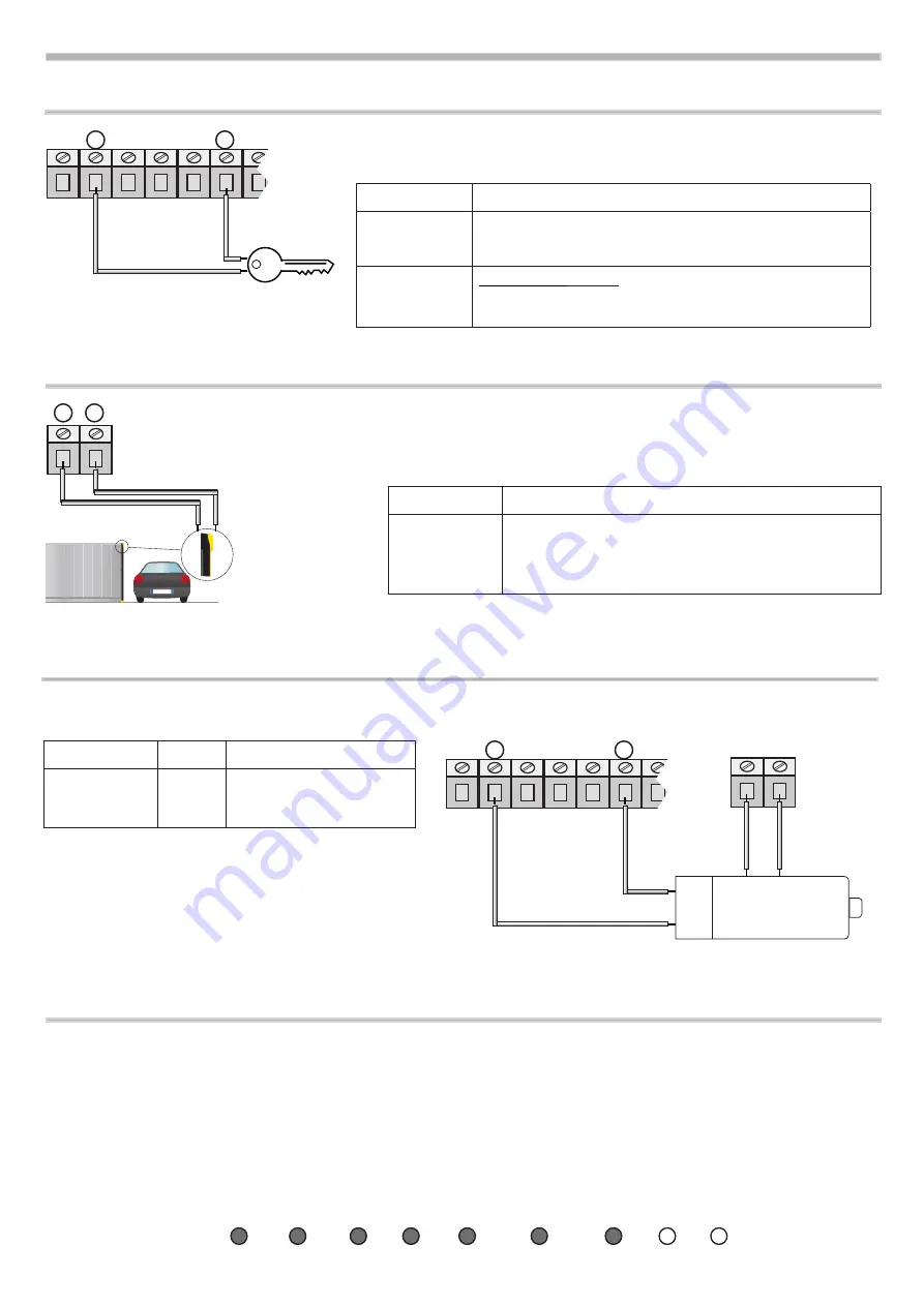
3.18 Connection of the MOTOR with ELECTRO-MAGNETIC BLOC
If the electro-magnetic block is available, go to function
S26
and put in
1
and make as follow:
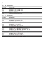
Set up
Value
Description
S 26
1
ELECTRO-MAgNETIC
BLOC
MOT
MOTOR
BRAKE
17 18 19
13 14 15 16
-
+
When this function will be activated and the motor is
working, the output of the KEY-LOCK will be powered,
this permet the brake and the correct working of the
gate.
3.16 Connection of the KEY LOCK
-
NEW LOCK SYSTEM
17 18 19
13 14 15 16
Here you can see the connections of the key-lock.
The function
S 26
should be programmed to “
0
”:
Set up
Description
S 26
0 -
Activate the
KEY LOCK
1 - Deactivate
the
KEY LOCK
(Default)
S 28
KEY LOCK
Power:
0 -
Power Supply 12V - Power Supply 12V key lock
1 -
Power Supply 24V - Power Supply 12V key lock
-
+
3.17 Connection of the Mechanical edge:
31 32
NOLOGO
Connection of the ALT control
Stops the automation and activates an inversion of direction for approxima-
tely 1.5 seconds.
Set up
Description
S 27
0 -
mechanical edge Deactivate
(Default)
1 - 8K2 contact
2 - 2 mechanical edge 8K2 connected in parallel
3 - N.C. contact
Summary of Contents for START S10
Page 21: ...NOTE 21 ...
Page 22: ...NOTE 22 ...
Page 45: ...NOTE 21 ...
Page 46: ...NOTE 22 ...
Page 67: ...NOTE 19 ...
Page 89: ...NOTE 21 ...
Page 90: ...NOTE 22 ...
Page 113: ...NOTE 21 ...
Page 114: ...NOTE 22 ...


