

9
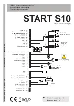
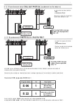
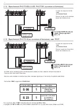
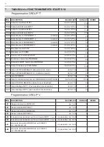
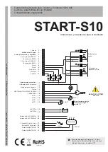
2.19 Check des branchement
il faut vérifier la tension des bornes, les lumières rouges s’allument, controller les sécurités, la direction du portail (avant le
portail OUVRE). Quand l’armoire est alimentée , les l.e.d sur les entrées, sont allumées quand il y a un contact fermé sur
le comun.
normalement les led rouges sur les entrées
fCC2 fCA2 - fCC1 - fCA1 - fOTOA - fOTOB – STOP
sont allumées.
normalement les led verts sur les entrées
START – PedonAle (ouverture partielle)
ne sont pas allumées.
fCC2 fCA2 fCC1 fCA1 fOTOA fOTOB STOP START PED
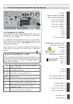
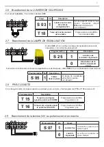
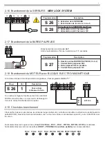
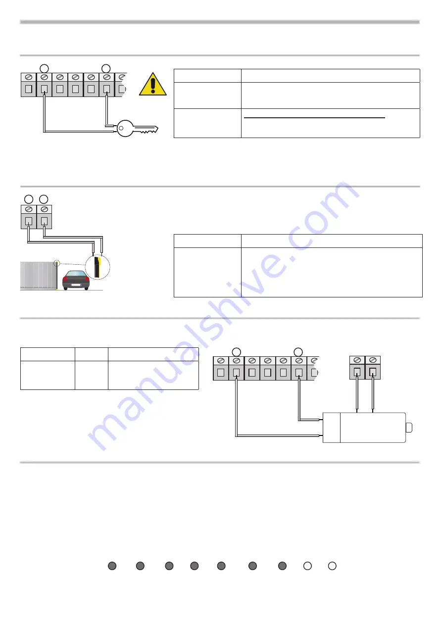
2.18 Branchement du MOTEUR avec BLOQUE ELECTRO-MAGnéTiQUE
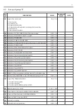
Si le moteur dispose d’un bloque electro-magnétique, il faut programmer
S26
à
“1”
Progr.
Val
description
S 26 1
Pour activer
le bloque du frein
MOT
MOTEuR
fRE
iN
17 18 19
13 14 15 16
-
+
Si on active cet type de fonctionnement, la sortie SER
-
RURE sera alimentée, et ça permet le déblocage du
frein et le correct fonctionnement du portai.
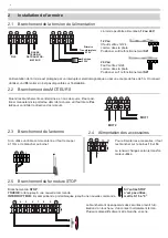
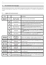
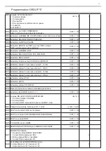
2.16 Branchement de la SERRURE
-
NEW LOCK SYSTEM
17 18 19
13 14 15 16
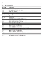
Programmation
description
S 26
0 - Activation de la
SERRuRE
1 - désactivation de la serrure
(Default)
S 28
Verrouillage de la
SERRuRE
électrique:
0 -
Alimentation à 12V, Serrure à 12V
1 -
Alimentation à 24V, Serrure à 12V
-
+
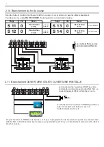
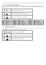
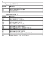
2.17 Branchement de la BARRE PALPEUSE
31 32
NOLOGO
Branchement de la commande
ALT
:
Arrête l’automatisme et fat une inversion pour 1,5 secondes.
Programmation
description
S 27
0 - déactivé entrée BARRe PAlPeUSe
(Default)
1 - Contact Barre palpeuse: 8K2
2 - Barre palpeus 8K2 en parallèle
3 - Contact Barre palpeuse: nC
Summary of Contents for START S10
Page 21: ...NOTE 21 ...
Page 22: ...NOTE 22 ...
Page 45: ...NOTE 21 ...
Page 46: ...NOTE 22 ...
Page 67: ...NOTE 19 ...
Page 89: ...NOTE 21 ...
Page 90: ...NOTE 22 ...
Page 113: ...NOTE 21 ...
Page 114: ...NOTE 22 ...


