(
23)
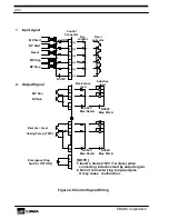
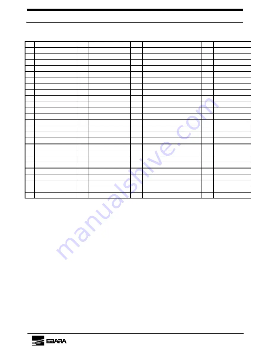
Table 4.5 Pin Assignment (Do not connect wires to unassigned pins.)
No
Signal name
I/O
Signal type
No
Signal name
I/O
Signal type
1
MP start
IN
N.O., Alternate *1
26 REMOTE/LOCAL OUT
N.O.,
Alternate
2
BP start *6
IN
N.O., Alternate *1
27
Casing Temp. (TRIP)
OUT
N.O., Alternate
3
ALARM/TRIP Reset
IN
N.O., Momentary *2
28
MP Motor Temp. (TRIP)
OUT
N.O., Alternate
4
MP Stop
IN
N.O., Momentary *1
29
BP Motor Temp. (TRIP) *6
OUT
N.O., Alternate
5
BP Stop *6
IN
N.O., Momentary *1
30
MP Overload (TRIP)
OUT
N.O., Alternate
6
COM of 1-5
IN
31
BP Overload (TIRP) *6
OUT
N.O., Alternate
7
32
Phase Error (TRIP)
OUT
N.O., Alternate
8
Emergency Stop *3
OUT
N.C., Alternate
33
9
COM of 8
OUT
34
Water Leak (TRIP) *3
OUT
N.O., Alternate
10
35
Exhaust Press. (TRIP) *3
OUT
N.O., Alternate
11
MP Operation
OUT
N.O., Alternate
36
12
BP Operation *6
OUT
N.O., Alternate
37
Water Flow (ALARM) *4
OUT
N.O., Alternate
13
38
Sealing
N
2
Flow (ALARM) *4
OUT
N.O., Alternate
14
COM of 11-12
OUT
39
Dilut. N
2
Flow (ALARM)
*4 *
5
OUT N.O.,
Alternate
15
40
Casing Temp. (ALARM)
OUT
N.O., Alternate
16
41
MP Current (ALARM)
OUT
N.O., Alternate
17
42
BP Current (ALARM) *6
OUT
N.O., Alternate
18
43
Oil Level (ALARM)
OUT
N.O., Alternate
19 TRIP/Collective OUT N.C.,
Alternate 44
20
COM of 19
OUT
45
Bearing Temp. (ALARM) *6
OUT
N.O., Alternate
21
46
22 ALARM/Collective OUT N.C.,
Alternate 47
23
COM of 22
OUT
48
24
49
25
50
COM of 26-45
OUT
MP = Main Pump, BP = Booster Pump.
Models A25S, A10S, A07V do not have a BP.
[NOTE]
*1 Dipswitch No. 5 selects external start / stop signal type.
Off : Alternate signal (Use only Pins 1 and 2.)
On : Pulse signal (Use Pins 1 and 2 for start and Pins 4 and 5 for stop,
Change Pins 1 and 2 to momentary signals with Dipswitch No. 5.)
In remote mode, select pump operation “according to signal” or “automatically stop” with
Dipswitch No.4.
Use Dipswitch No.8 to configure remote BP operation as “automatic” or “according to
signal.”
*2 Input signal duration for Pin No. 3 (ALARM / TRIP Reset) and Pins No. 1, 2, 4, and 5
(Momentary Start / Stop) is 200ms.
*3 Pins No. 8 (Emergency Stop Switch), 34 (Water Leakage), and 35 (Exhaust Pressure)
are for options. Pin No. 8 (Emergency Stop Switch) output remains OFF until the switch
is closed and a RESET signal is entered.
*4 Dipswitch No.2 selects observation of cooling water and N
2
gas flow as “always” or
“operating period only.”
EBARA
Corporation
Summary of Contents for A70W
Page 9: ...vii EBARA Corporation...
Page 10: ...viii EBARA Corporation...
Page 11: ...ix EBARA Corporation...
Page 14: ...xii Blank page EBARA Corporation...
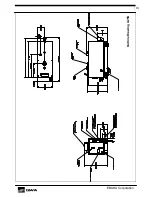
Page 21: ...7 EBARA Corporation Outline Drawing A70W...
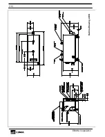
Page 22: ...8 Outline Drawing A30W EBARA Corporation...
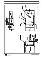
Page 23: ...9 EBARA Corporation Outline Drawing A25S...
Page 24: ...10 EBARA Corporation Outline Drawing A10S...
Page 25: ...11 EBARA Corporation Outline Drawing A07V...
Page 60: ...46 Blank Page EBARA Corporation...
Page 63: ...III Label Country US Label Emergency Number 716 293 3330 EBARA Corporation...

