background image

7

EN

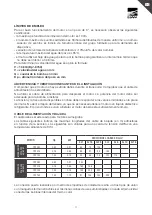
USE LIMITATIONS 

For good operating of the motor, installed in a 3” well, it is necessary to follow these conditions: 
- maximum depth of motor immersion is 100m.
- maximum allowable starts per hour: 30 at even intervals; an upper quantity means that the 

programming of the hydraulic system is wrong.

- maximum allowable rating voltage fluctuation: -10%/+6%.
- maximum well water temperature: 35°C.
- the electric motor utilizes the water flow, produced by the pump, to assure a suitable heat 

exchange not lower than 0.08m/sec.

It’s possible to determine water speed applying the following formula: 

V = 10.6Q/(Dp²-8760)
V = water flow speed (m/sec.)
Q = flowrate (lt/min)
Dp = well inner diameter (mm)

PRECAUTIONS AND PRELIMINARY CHECKS 


During transportation and unpacking, care should be taken to avoid hitting the motor.
Check that the power cable has not been damaged.
Don’t use the power cable to make the motor handling.
Motor power rating is adeguate for the required application.
The voltage and the frequency of the power source must agree with the specifications given on the 
motor nameplate.
Don’t unscrew the filling plug, there is no need to top up the coolant in this type of motor.
Clean up the well before installation of the motor-pump.

POWER CABLE AND DROP  


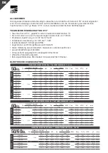
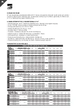
The power supply cable must be suitable to immersion. The diagram below show the maximum 
possible admitted length of the cable (unit of measure m) possible considering the cross section 
of the conductors. Those schedules are true for a maximam voltage drop of3%with a working 
temperature of 30°C.

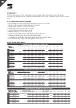
MOTOR

Hp

kW

DROP CABLE SECTION mm²

4x1

4x1.5 4x2.5

4x4

4x6

4x10

4x16

SI

NG

LE P

H.

V22

0-

23

0

50

/6

0 H

Z

OY3 050

0,50

0,37

50

75

125

OY3 075

0,75

0,55

38

57

95

152

OY3 100

1,00

0,75

30

45

75

120

174

TH

RE

E P

H.

V3

80

-4

00

50

/6

0 H

Z

OY3 050

0,50

0,37

240

OY3 075

0,75

0,55

164

246

OY3 100

1,00

0,75

133

200

333

OY3 150

1,50

1,10

97

146

244

390

Splicing the drop cable to the motor cable must be carried out through suitable resin filled kit, 
following the producer’s instructions and do not forget to join the core cable with the same colour 
(black-blue-brown).

Summary of Contents for OY3 Series

Page 1: ...E MOTOR OY3 SERIES 1200N Installation manual MOTOR SUMERGIDO SERIE OY3 1200N Manual de instalacion MOTEUR IMMERG S RIE OY3 1200N Notice d installation TAUCHMOTOR SERIE OY3 1200N Installationsanleitung...

Page 2: ...37 0 5 2 40 8 0 2800 0 71 2 1 51 OYM 075 6 1 377 0 55 0 75 2 50 9 1 0 75 2 56 OYM 100 6 4 397 0 75 1 2 90 11 7 0 75 2 63 OYM 150 6 8 416 1 1 1 5 3 60 14 0 0 75 2 63 220 OYM 050 3 1200 6 377 0 37 0 5...

Page 3: ...essere adeguata alla pompa da installare La tensione e la frequenza disponibili in linea devono corrispondere con quelli specificati nella targa delmotore Non aprire il tappo di riempimento in quanto...

Page 4: ...it degli stessi nel quadro elettrico di comando U1 Nero V1 Blu W1 Marrone Terra Giallo Verde Seguono in allegato gli schemi elettrici scheda dimensionale Ebara Pumps Europe S p A si riserva di cambiar...

Page 5: ...avvolgimenti danneggiati Riparare o sostituire il componente danneggiato Fusibili o interruttore automatico sottodimensionato Sostituire con componentiidonei Diversa tensione di alimentazione Usare al...

Page 6: ...1 377 0 55 0 75 2 50 9 1 0 75 2 56 OYM 100 6 4 397 0 75 1 2 90 11 7 0 75 2 63 OYM 150 6 8 416 1 1 1 5 3 60 14 0 0 75 2 63 220 OYM 050 3 1200 6 377 0 37 0 5 4 15 14 0 2800 0 71 2 1 51 OYM 075 6 1 377...

Page 7: ...plication The voltage and the frequency of the power source must agree with the specifications given on the motor nameplate Don t unscrew the filling plug there is no need to top up the coolant in thi...

Page 8: ...tion to the following cable label and carry out the same sequence on the power control box terminal board U1 Black V1 Blue W1 Brown Earth Yellow Green Follow enclosed electric diagram dimension sketch...

Page 9: ...ed previously Reset protection Defective motor winding or power cable Repair or replace the faulty unit Unsuitable fuses or automatic switch Replace with suitable units Supply voltage incorrect Change...

Page 10: ...2 40 8 0 2800 0 71 2 1 51 OYM 075 6 1 377 0 55 0 75 2 50 9 1 0 75 2 56 OYM 100 6 4 397 0 75 1 2 90 11 7 0 75 2 63 OYM 150 6 8 416 1 1 1 5 3 60 14 0 0 75 2 63 220 OYM 050 3 1200 6 377 0 37 0 5 4 15 14...

Page 11: ...tor La potencia del motor debe ser adecuada para la bomba a instalar La tensi n y la frecuencia disponibles en l nea deben responder a los valores indicados en la placa del motor No abrir el tap n de...

Page 12: ...ro V1 Azul W1 Marr n Tierra Amarillo Verde Acontinuaci n se adjuntan los esquemas el ctricos ficha de medidas Ebara Pumps Europe S p A se reserva la facultad de cambiar las caracter sticas t cnicas si...

Page 13: ...Reparar o sustituir el componente da ado Fusibles o interruptor autom tico subdimensionados Sustituir con componentes adecuados Diferente tensi n de alimentaci n Utilizar otra fuente de alimentaci n...

Page 14: ...40 8 0 2800 0 71 2 1 51 OYM 075 6 1 377 0 55 0 75 2 50 9 1 0 75 2 56 OYM 100 6 4 397 0 75 1 2 90 11 7 0 75 2 63 OYM 150 6 8 416 1 1 1 5 3 60 14 0 0 75 2 63 220 OYM 050 3 1200 6 377 0 37 0 5 4 15 14 0...

Page 15: ...senken oder daraus hervorzuholen Die Motorleistung muss der zu installierenden Pumpe entsprechen Spannung und Frequenz m ssen denWerten auf demTypenschild des Motors entsprechen Einf llstutzen nicht f...

Page 16: ...alten ist U1 Schwarz V1 Blau W1 Braun Schutzleiter Gelb Gr n AlsAnlage folgend die Schaltpl ne und Ma zeichnungen Ebara Pumps Europe S p A beh lt sich das Recht vor die technischen Eigenschaften unang...

Page 17: ...igte Komponente reparieren oder austauschen Sicherungsautomat unterdimensioniert Durch geeignete Komponenten ersetzen Andere Versorgungsspannung Eine andere Stromversorgungsquelle verwenden oder Motor...

Page 18: ...2800 0 71 2 1 51 OYM 075 6 1 377 0 55 0 75 2 50 9 1 0 75 2 56 OYM 100 6 4 397 0 75 1 2 90 11 7 0 75 2 63 OYM 150 6 8 416 1 1 1 5 3 60 14 0 0 75 2 63 220 OYM 050 3 1200 6 377 0 37 0 5 4 15 14 0 2800 0...

Page 19: ...aller La tension et la fr quence du r seau lectrique doivent correspondre aux valeurs indiqu es sur la plaque signal tique du moteur Ne pas ouvrir le bouchon de remplissage parce qu il ne faut pas ajo...

Page 20: ...r V1 Bleu W1 Marron Terre Jaune Vert les sch mas lectriques plan cot sont joints cette notice Ebara Pumps Europe S p A se r serve le droit de modifier les caract ristiques techniques de ses produits s...

Page 21: ...nes endommag s R parer ou remplacer le composant endommag Fusibles ou disjoncteur sous dimensionn s Remplacer par des composants adapt s Tension d alimentation incorrecte Utiliser une autre source d a...

Page 22: ...0 6 377 0 37 0 5 2 40 8 0 2800 0 71 2 1 51 OYM 075 6 1 377 0 55 0 75 2 50 9 1 0 75 2 56 OYM 100 6 4 397 0 75 1 2 90 11 7 0 75 2 63 OYM 150 6 8 416 1 1 1 5 3 60 14 0 0 75 2 63 220 OYM 050 3 1200 6 377...

Page 23: ...j pompy Napi cie oraz cz stotliwo zasilania musz odpowiada warto ciom podanym na tabliczce silnika Nie otwiera korka wlewu poniewa dolanie do silnika ch odziwa dielektrycznego nie jest konieczne Studn...

Page 24: ...ich kra ce na elektrycznej tablicy sterowniczej U1 Czarny V1 Granatowy W1 Br zowy Uziemienie tozielony W za czniku schematy elektryczne karta wymiarowa Firma Ebara Pumps Europe S p A zastrzega sobie p...

Page 25: ...nia Naprawi lub wymieni uszkodzony komponent Niedostateczne rozmiary bezpiecznika lub wy cznika automatycznego Wymieni na odpowiednie komponenty Inne napi cie zasilania U y innego r d a zasilania lub...

Page 26: ...3 EBARA OY3 60 60Hz H In Cos Ts Tn F Imax N mm A 220 230 OYM 050 1 1200 6 377 0 37 0 5 3 80 9 3400 0 96 0 54 51 12 5 5 2 OYM 075 6 4 397 0 55 0 75 4 60 13 0 98 0 52 55 16 6 0 OYM 100 6 8 416 0 75 1 5...

Page 27: ...1 4x1 5 4x2 5 4x4 4x6 4x10 4x16 220 230 50 60 OY3 050 0 50 0 37 50 75 125 OY3 075 0 75 0 55 38 57 95 152 OY3 100 1 00 0 75 30 45 75 120 174 380 400 50 60 OY3 050 0 50 0 37 240 OY3 075 0 75 0 55 164 24...

Page 28: ...28 RU 1 5 1 OY3 U1 V1 W1 Ebara Pumps Europe S p A 2012 19...

Page 29: ...29 RU Ebara Ebara Pumps Europe S p A...

Page 30: ...30...

Page 31: ...31...

Page 32: ...plant the installer must the conformity of the system in its entirely DECLARACI N DE CONFORMIDAD CE EBARA PUMPS EUROPE S p A con sede en Via Campo Sportivo 30 38023 Cles TN ITALIA declara bajo su prop...

Page 33: ......

Page 34: ...787 0110815 0071381 0071382 0071383 03 07 2014 02 07 2019 RU C IT 30 01844 0288871 0209871 0209872 0209873 0209874 0209875 0209876 0209877 0209878 0209879 0209880 0209881 14 08 2015 13 08 2020 153032...

Page 35: ...35...
Page 36: ...land Tel 48 22 3909920 Fax 48 22 3909929 e mail mktgpl ebaraeurope com EBARA Pumps Europe S p A GERMANY Elisabeth Selbert Stra e 2 63110 Rodgau Germany Tel 49 0 6106 66099 0 Fax 49 0 6106 66099 45 e m...

Reviews: