8
EN
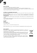
INSTALLATION
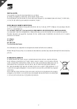
Normal working position of the OY3” series motor is vertical.
Drop cable must be secured to the riser pipe at intervals no longer than 1.5m
Motor must be positioned, for a correct cooling, at a distance of about 1 m to the well bottom to
avoid accumulation of sand and mud.
ELECTRIC CONNECTION DIAGRAM
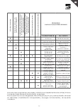
Below it is possible to see electric connection diagram of OY3” motors three phase(D.O.L.) and
single phase.
We underline that the connections must be executed by QUALIFIED AND EXPERIENCED
PERSONNEL.
It’s very important to make earth connection of the electric motor in adherence with the existing
standards.
Pay attention to the following cable label and carry out the same sequence on the power control
box terminal board:
U1 = Black
V1 = Blue
W1 = Brown
Earth = Yellow/Green
(Follow enclosed electric diagram, dimension sketch)
Data eventually changeable without prior notice.
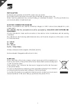
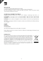
DISPOSAL
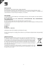
When disposing of the motor, please comply rigorously with the regulations in
force in your country. This symbol on the motor means that it cannot be disposed
of with household waste.
This provision only concerns the disposal of equipment within the European
Union (2012/19/EU).
The user is responsible for disposing of the equipment by taking it to a collection
and recycling facility authorized to dispose of electrical waste.
For further information on equipment collection points, contact your local waste
disposal authority or the store that you purchased the product from.
Summary of Contents for OY3 Series
Page 28: ...28 RU 1 5 1 OY3 U1 V1 W1 Ebara Pumps Europe S p A 2012 19...
Page 29: ...29 RU Ebara Ebara Pumps Europe S p A...
Page 30: ...30...
Page 31: ...31...
Page 33: ......
Page 35: ...35...


