background image


Page 10


Electric diagram 
Manual flushing MOD: GS-21 III 
AB of the machine No. 
 
B1 

Switch Commissioning 

B4 

Micro door 

B6 

Switch 

B7 

Push button Manual rinsing 

B8 

Button manual rinsing 

Motor capacitor 

C1 

Heater protection water heater 

C2 

Heater protection tank 

C4 

Contactor heating 

CM 

Relay micro door 

C5 

Pump capacitor rinsing 

C6 

Manual rinsing relay 

D1 

Program switch 

E2 

Thermostat temperature controller tank 

E3 

Level pressure regulator 

F1 

Fuse 

F3 

Filter anti-parasite capacitor 

H1 

Indicator commissioning 

H2 

Indicator rinsing program 

H5 

Indicator correct temperatures 

H6 

Indicator light manual rinsing 

H7 

Indicator rinsing 

M1 

Rinsing motor 

M3 

Motor flushing pump (optional) 

R1 

Heater water heater 

R2 

Heater tank 

Y1 

Filling / flushing electric valve 

Y4 

Cleaning agent dispenser 

T2 

Program switch flushing 

T3 

Program switch rinsing 

T4 

Manual program switch flushing 


Summary of Contents for GS 21

Page 1: ...nsing nozzles Page 17 18 Please read all of the Operating Instructions before using the machine Technical changes reserved Operating Instructions Bottle rinsing machine GS 21 Edition November 2020 Erich Baumgartner Gastronomiemaschinengroßhandel Hauptstraße 4 A 5222 Munderfing Phone 0043 0 664 18 16 5 18 Fax 0043 7744 20 12 12 E mail erich gastrohandel at Inventor of the bottle washing machine wit...

Page 2: ...m The machine has to be levelled with the height adjustable feet Check the correct position inside the machine basket slipway with a spirit level not on the housing It is necessary that the door can be opened and closed with ease Remove the white protective film from the machine The water inlet water outlet power cable as well as the hose for the dosing medium are pre installed in the machine The ...

Page 3: ...ed with a split pin ATTENTION PULL THE MAINS PLUG DO NOT REACH INSIDE THE MACHINE The dosing pump is located behind the panel at the left front Please check if the setting of the dosing is the same as in the picture on the left Position the arrow to 1 o clock Otherwise set with a small screwdriver as illustrated If the machine is delivered in the cold season the axial wheel might get stuck on In t...

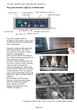
Page 4: ... Rinsing Dosing of the Cleaning Chemicals Re rising When the rinsing process is completed 6 min 30 sec the control lamp 5 is switched off and the machine can be used for another rinsing process as soon as the controlling lamp 4 is illuminated again Depending on how much dirt is on the bottles or crates the machine can reuse the same soapy water If the soapy water got too dirty it would be necessar...

Page 5: ...d slightly pull them out of the bayonet insertion Make sure that the water drains at even amounts and rapidly out of the tank After finishing work the machine has to be drained Do not leave soapy water in the machine any longer than it is necessary ATTENTION THE WATER TEMPERATURE IN THE TANK COULD BE MORE THAN 53º C THERE IS A RISK OF MINOR BURNS Remove the surface filters and remove the labels an...

Page 6: ...t Page 6 To perform the cleaning it is recommended to place the beer crates on the crate carrier included in the delivery The beer crates should be cleaned at the end of the bottle rinsing process If the soapy water is very dirty replace it first refer to Draining the Machine Insert the overflow pipe into the door frame so that the interior may air ...

Page 7: ...er pressure The exterior of the machine should only be wiped with a damp cloth Please observe that life switches and control lights are in the area of the operating panel Decalcifying the interior of the machine The supply system of the machine is only supplied with cold water Therefore it is not necessary to decalcify this area Decalcify the machine as follows Clean the interior of the machine re...

Page 8: ...Page 8 ...

Page 9: ...Page 9 ...

Page 10: ...nual rinsing relay D1 Program switch E2 Thermostat temperature controller tank E3 Level pressure regulator F1 Fuse F3 Filter anti parasite capacitor H1 Indicator commissioning H2 Indicator rinsing program H5 Indicator correct temperatures H6 Indicator light manual rinsing H7 Indicator rinsing M1 Rinsing motor M3 Motor flushing pump optional R1 Heater water heater R2 Heater tank Y1 Filling flushing...

Page 11: ... Volt Tank contents 29 ltr Water consumption rinsing cycle about 8 7 ltr Water pressure permanent flow pressure 2 5 bar Water supply line Water outlet 50 mm Rack height Bottles of up to 400 mm Basket dimensions 500 x 500 mm Equipment of baskets 1 bottle basket 1 crate carrier for bottle crates Dimensions Width 580 mm Depth 630 mm Height without feet 820 mm Height incl feet 830 mm Page 11 ...

Page 12: ...cked NF or flip top bottles wine bottles juice bottles milk bottles yoghurt jar and much more Page 12 Scope of delivery 1 pcs Basic basket 8 pcs Support rails 36 pcs Supporting bars 88 pcs screws washers reserve 1 pcs Template for the basket mounting 1 pcs Screw connection for rinsing arm 1 pcs Magnet 1 pcs Cable tie per basket ...

Page 13: ...n put your bottle in our example a 0 75 l flip top bottles on the recess of the template Then mount the support rail at the height which best allows to hold the bottle at the bottle neck Then mount the lateral and rear support rail Attention Mount the front and rear support rails at the same height and fix them with the screws Only tighten the screws slightly Mount the lateral support rails displa...

Page 14: ...upport bar exactly matches with the recesses of the template Page 14 Place the support bars on the bottom level of the support rails Up to 10 pcs depending on the size of the bottle Then position the support bars 2 pcs each at the 5 recesses of the template from the front to the rear Take one screw with one washer each and mount the support bars Only slightly tighten the screws in order to be stil...

Page 15: ...ways check the exact position of the bottle mouth with the recess of the template If it matches you can tighten the screws on the support bars When using a cordless screwdriver it is recommended not to use the maximum torque output of the cordless screwdriver As soon as the bottom level of the bottle basket is assembled you can assemble the upper level of the bottle basket ...

Page 16: ...bottom on the basket frame Then place the support bars from the left to the right as well as from the front to the rear on the support rails When inserting the bottles into the upper level always make sure that they need to stand up straight or slightly inclined to the left in the bottle basket Important Bottles with the same bottle neck or bottle diameter but different heights can be used in the ...

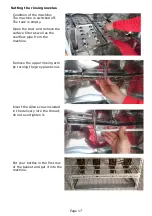
Page 17: ...en the door and remove the surface filter as well as the overflow pipe from the machine Remove the upper rinsing arm by turning the grey plastic nut Insert the Allen screw included in the delivery into the thread do not overtighten it Put your bottles in the first row of the basket and put it into the machine ...

Page 18: ...of the rinsing nozzles sprays directly into the bottle mouth If one or several rinsing arms do not spray into the bottle opening take an open end spanner wrench opening 20 loosen the nut of the arm and turn it into the correct position The rinsing arm can be turned laterally to the left and to the right and extracted or slided in After having set the rinsing nozzles mount the top rinsing arm on th...

Reviews: