background image

14

DE

EN

FR

ES

IT

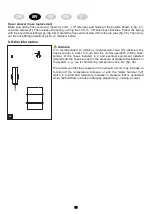
For installing the hose reel make sure that the support surface is flat and check that the wall is suitable for
supporting the weight of the reel.

Connection of the hose reel to the distribution system tubing must be carried out using suitable fittings and
tight sealant in the connection points (e.g. Teflon® and Loctite®).

Remember that frequent bending of the hose at very tight angles could eventually compromise the integrity
of the hose, facilitating cracking.

During rewinding, the hose

must always be guided by hand, it is forbidden to release the hose during

the rewinding phase,

to avoid subjecting the hose to impact or abrasions that may compromise its

integrity and to avoid damage to people or things.

Do not expose the hose to heat sources, and protect it from mechanical impacts possible in relation to the
place of installation.

Our hose reel may be installed externally. Installations carried out under shelving and roof eves will protect
the hose from premature ageing caused by atmospheric conditions.

Depending on the model, hose reels are intended to be used:

For work with compressed air, such as painting, spraying, inflating tyres and the use of screwers,
pneumatic hammers, riveters, etc.

For work with water, such as washing (cars and other vehicles, toilets, butchering meat, cellars, etc.).

All the hose reel models are also intended for use in underground places and surface plants of mines where the
risk of firedamp, coal dust and/ or other flammable gases and dusts is prevented by other appropriate prevention
systems (e.g. effective and reliable ventilation systems).

The equipment can be used in standard en vironmental conditions (temperature range -20 °C ÷ +40 °C,
-4°F÷104 °F). Use of conductive or dissipative hoses is mandatory (resistance lower than 50 MΩ) for installation
in areas where it is required to comply with the Atex directive.

Hose reels for use with flammable gas and liquids are ARE NOT:

They are not suitable for installation in the presence of internal and/or external explosive environments
caused by flammable gas classified as zone 0 (in compliance with 99/92/CEE - 2014/34/UE).

They are not suitable for installation in the presence of internal and/or external explosive atmospheres
caused by flammable dust classified as zone 20 (in compliance with 99/92/CEE - 2014/34/UE).

They are not intended for underground works in the mining industry or surface facilities that may be
exposed to the risk of release of firedamp and/or flammable dust (coal dust).

The versions suitable for transportation of flammable liquids ARE NOT suitable for liquids other than
gasoline and benzines.

The versions suitable for transportation of flammable gas ARE NOT suitable for gas other than
manufactured gases or city gas, natural gas or methane, liquefied petroleum gas (LPG) (1°, 2°, 3°,
category UNI EN 437).

This equipment is not intended for suction/delivery of fluids with temperatures at the hose reel input above
the expected limits (see E.1 Equipment’s intended use).

This equipment is not intended to work with pressures above the expected limits (see E.1 Equipment’s
intended use).

1. General warnings

2. Foreseen use and limitations of use

Carefully read this instruction booklet before using the
equipment!

Summary of Contents for 1.610.131

Page 1: ...istruzioni Avvolgitubo OSM OSK ES Manual de instrucciones Enrolladores OSM OSK FR Manual de mode d emploi Enrouleurs OSM OSK GB Instruction booklet Hose reel OSM OSK DE Bedienungsanleitung Schlauchauf...

Page 2: ...Instructions generales 23 2 Utilisation prevue et limites d utilisation 23 3 Entretien et controles 24 4 Description d enrouleurs de tuyau sans bo tier 25 5 Description de l enrouler avec carter 26 6...

Page 3: ...s Explosion protection level for gas Niveau de protection explosions pour gaz Nivel de protecci n contra explosiones de gas Livello di protezione esplosioni per gas H chsttemperatur Au en fl chen und...

Page 4: ...adtgas Gascombustibles gpl butano gasciudad Gasescombust veis gpl metano g s de cidade 40 C 104 F Liquidi combustibili benzine e gasoli Combustible liquids gasolineand benzines Liquides combustibles e...

Page 5: ...eisetzung von Grubengas Kohlenstoffst uben u o anderen entflammbaren Gasen und St ben durch geeignete Systeme ausgeschlossen ist z B wirkungsvolle und zuverl ssige Bel ftungssysteme Die Verwendung des...

Page 6: ...wird Bei Schlauchaufrollern die f r Druckluft oder Fl ssigkeiten wie Wasser oder Diesel verwendet werden muss vor dem Schlauchaufroller ein Filter installiert werden damit keine Verunreinigungen in de...

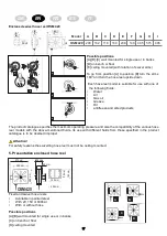
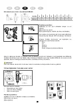
Page 7: ...Stahl lackiert mit 20 100 150 200 400 600 und 700bar Edelstahl mit 20 100 150 200 400 600 und 700bar Mit und ohne Schlauch 4 Beschreibung Schlauchaufroller ohne Geh use Abmessungen des FESTSTEHENDEN m...

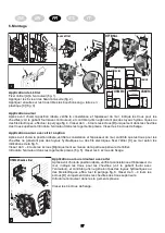
Page 8: ...ng Aus Sicherheitsgr nden darf der Schlauchaufroller in der verstellbaren Ausf hrung nicht an der Decke montiert werden 5 Beschreibung Schlauchaufroller mit Geh use Fest montierter und schwenkbarer Sc...

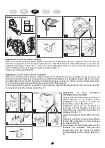
Page 9: ...nen Dann den B gel C an der Wand befestigen siehe Abb 5 Die Muttern D mit 3 bis 4 Umdrehungen auf die oberen Schrauben drehen Den Schlauchaufroller einsetzen Abb 5 und durch Anziehen der 4 Befestigung...

Page 10: ...n Seegersicherungen an wie in Abb 11 zu sehen ist Der so montierte Aufroller kann frei um 55 nach rechts und links geschwenkt werden Wenn der Aufroller in der Position nicht schwenkbar angebracht werd...

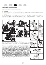
Page 11: ...Nippel mit Schlauch wieder einsetzen und dazu einen Schl ssel verwenden Abb 22 Die 3 Schrauben F l sen Abb 23 In den Sitz vom zentralen Stift einen 8 er 5 16 Inbusschl ssel einsetzen Abb 24 Durch Dreh...

Page 12: ...32 29 31 Schlauch auswechseln Die oben genannten Arbeitsschritte zur Befestigung vom Schlauch in umgekehrter Reihenfolge durchf hren N 35 36 37 F 42 40 38 39 41 N 35 36 37 F 42 40 38 39 41 44 43 44 F...

Page 13: ...l im Uhrzeigersinn drehen Beim L sen der Federspannung den Inbusschl ssel gut festhalten Abb 44 Den Schlauch abwickeln und vom Nippel Abb 45 abschrauben Den neuen Schlauch wie auf Seite 36 bis 43 besc...

Page 14: ...y other appropriate prevention systems e g effective and reliable ventilation systems The equipment can be used in standard en vironmental conditions temperature range 20 C 40 C 4 F 104 F Use of condu...

Page 15: ...trostatic charges in the hose reel 3 Maintenance and checks TEST 3 TEST 2 TEST 1 TEST 3 TEST 2 TEST 1 Before commissioning the hose reel check the earthing in order to guarantee protection against ris...

Page 16: ...0 300 218 227 268 165 535 510 572 315 OSM 710 488 399 238 272 348 535 510 578 315 OSK 400 186 140 197 226 110 450 425 461 259 OSK 500 203 153 221 258 121 535 510 558 327 Fixed hose reel OSM OSK Abmess...

Page 17: ...mproper Attention For safety reasons the swivelling hose reel must not be ceiling mounted 5 Presentation enclosed hose reel Fixed and swivel hose reels Available in painted steel With 20 150 or 600bar...

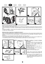
Page 18: ...wall as shown in fig 5 Screw the nuts D 3 4 turns only on the upper part of the bracket Insert the hose reel in the special seats fig 5 Tighten the 4 fixing nuts Wall mounting enclosed hose reel After...

Page 19: ...ivel hose reel fig 8 9 Hook the hose reel and apply the two safety snap rings as shown in fig 11 The hose reel thus mounted can be freely turned 55 to the right left If the hose reel is to be installe...

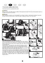
Page 20: ...nipple with the hose using a spanner fig 22 Remove the 3 screws F fig 23 Insert an 8 mm 5 16 Allen key in the seat of the middle pin fig 24 Turning the key anticlockwise turns the drum that will wind...

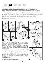
Page 21: ...42 40 38 39 41 44 43 44 F F 45 Hose fitting enclosed hose reel OSM 420 Place the hose reel as shown in fig 35 and remove the hose inspection casing Screw the nipple N on the drum using a sealant fig 3...

Page 22: ...nformation Attention It is recommended to install an overpressure valve X upstream the hose s winder in order to main tain the normal operation of the hose winder of the hoses installed in it and even...

Page 23: ...mini res o le risque de d gagement de grisou poussi res de charbon et ou autres gaz et poussi res inflammables soit emp ch s par d autres syst mes de pr vention appropri s par exemple des syst mes de...

Page 24: ...constitue un danger potentiel pour l op rateur si elle n est pas effectu e par du personnel express ment form Pour les enrouleurs employ s avec des fluides comme l air l eau ou le gazole il faut pr vo...

Page 25: ...150 200 400 600 und 700bar Disponibles en acier inox avec 20 100 150 200 400 600 und 700bar Vvec et sans tuyau 4 Description Enrouleurs de tuyau sans bo tier mod le A B C D E F G H I OSM 210 186 140 1...

Page 26: ...sid r e comme incorrecte Attention Pour des raisons de s curit l enrouleur version orientable ne doit pas tre mont au plafond 5 Description de l enrouler avec carter Enrouler fixe et orientable Dispon...

Page 27: ...selon les indications de la fig 5 Visser de 3 4 tours les crous D uniquement au niveau de la partie sup rieure de l trier Introduire l enrouleur dans les logements pr vus fig 5 Visser les 4 crous de...

Page 28: ...ig 8 9 Accrocher l enrouleur et appliquer les deux anneaux de retenue comme indiqu dans la fig 11 L enrouleur ainsi mont peut librement tourner de 55 droite gauche Si l enrouleur doit tre install en p...

Page 29: ...lisant une clef fig 22 Enlever les 3 vis F fig 23 Introduire dans le logement du pivot central une clef hexagonale de 8 mm 5 16 fig 24 En tournant la clef dans le sens inverse des aiguilles d une mont...

Page 30: ...cement du tuyau R p ter l inverse les op rations de montage tuyau indiqu es ci dessus N 35 36 37 F 42 40 38 39 41 N 35 36 37 F 42 40 38 39 41 44 43 44 F F 45 Montage du tuyau enrouleur avec carter OSM...

Page 31: ...sans le laisser s chapper fig 44 D rouler le tuyau et le d visser des nipples fig 45 Effectuer ensuite les op rations de montage du tuyau indiqu es de la page 36 la page 43 46 X 8 Autres indications A...

Page 32: ...e difusi n de gris polvos de carb n y u otros gases y polvos inflamables sea evitado por otros adecuados sistemas de prevenci n por ejemplo eficaces y fiables sistemas de ventilaci n La utilizaci n de...

Page 33: ...ctuada por personal especialmente preparado Para los enrollatubos utilizados con fluidos como aire agua o gasoil prever un filtro a monte del enrollatubo para evitar la entrada de im purezas que puede...

Page 34: ...do con 20 100 150 200 400 600 y 700bar Disponible en acero inox con 20 100 150 200 400 600 y 700bar Con y sin tubo 4 Presentaci n entrollatubo sin carter Modelo A B C D E F G H I OSM 210 186 140 196 2...

Page 35: ...onsidera incorrecto Atenci n Por razones de seguridad la versi n de enrollatubos orientable no puede instalarse en el techo 5 Presentaci n enrollatubo con carter Enrollatubo fijo y orientable Disponib...

Page 36: ...pared seg n se indica en la fig 5 Atornillar con 3 4 vueltas las tuercas D s lo en la parte superior de la abrazadera Introducir el enrollatubo en sus alojamientos fig 5 Atornillar las 4 tuercas de su...

Page 37: ...entable fig 8 9 Enganchar el enrollador y aplicar los dos seegers de seguridad como indicado en fig 11 El enrollador as montado puede rotar libremente 55 derecha izquierda Si el enrollador est instala...

Page 38: ...tubo utilizando una llave fig 22 Quitar los 3 tornillos F fig 23 Introducir en el alojamiento del perno central una llave hexagonal de 8 mm 5 16 fig 24 Girando la llave en sentido antihorario se hace...

Page 39: ...tubo Repetir a la inversa las operaciones de montaje tubo explicadas arriba N 35 36 37 F 42 40 38 39 41 N 35 36 37 F 42 40 38 39 41 44 43 44 F F 45 Montaje tubo enrollatubo con carter OSM 420 Apoyar e...

Page 40: ...r el resorte con la llave sin que se escape fig 44 Desenrollar el tubo y desenroscarlo del niple fig 45 Efectuar luego las operaciones de montaje tubo descritas de pag 36 a 43 46 X 8 Notas miscel neas...

Page 41: ...e laddove il rischio di sprigionamento di gris polveri di carbone e o altri gas e polveri infiammabili sia precluso da altri adeguati sistemi di prevenzione per esempio efficaci ed affidabili sistemi...

Page 42: ...tenzioni e controlli TEST 3 TEST 2 TEST 1 TEST 3 TEST 2 TEST 1 Prima della messa in servizio dell avvolgitubo effettuare il controllo della messa a terra in modo da garantire la protezione contro i ri...

Page 43: ...04 535 510 558 315 OSM 610 300 218 227 268 165 535 510 572 315 OSM 710 488 399 238 272 348 535 510 578 315 OSK 400 186 140 197 226 110 450 425 461 259 OSK 500 203 153 221 258 121 535 510 558 327 Avvol...

Page 44: ...ione Per motivi di sicurezza la versione di avvolgitubo orientabile non deve essere montata a soffitto 5 Presentazione avvolgitubo carterato fisso e orientabile Disponible in acciaio verniciato Con 20...

Page 45: ...muro come indicato in fig 5 Avvitare di 3 4 giri i dadi D solo nella parte superiore della staffa Inserire l avvolgitubo nelle apposite sedi fig 5 Avvitare i 4 dadi di fissaggio Applicazione a muro av...

Page 46: ...e fig 8 9 Agganciare l avvolgitubo ed applicare i due seegers di sicurezza come indicato in fig 11 L avvolgitubo cos montato pu liberamente ruotare di 55 destra sinistra Se l avvolgitubo va installato...

Page 47: ...pple con il tubo utilizzando una chiave fig 22 Togliere le 3 viti F fig 23 Inserire nella sede del perno centrale una chiave esagonale da 8 mm 5 16 fig 24 Girando la chiave in senso antiorario si fa g...

Page 48: ...o sostituzione tubo Ripetere a ritroso le operazioni di montaggio tubo sopra riportate N 35 36 37 F 42 40 38 39 41 N 35 36 37 F 42 40 38 39 41 44 43 44 F F 45 Montaggio tubo avvolgitubo carterato OSM...

Page 49: ...arla sfuggire fig 44 Sro tolare il tubo e svitarlo dal nipples fig 45 Eseguire quindi le opera zioni di montaggio tubo riportate vedi capitoli precedenti 46 X 8 Note varie Attenzione Si consiglia di i...

Page 50: ...on ATEX Dans le cas de l achat d un mod le sanstuyau un tuyau de dissipation antistatique doit tre install pour confirmer le degr de protection ATEX Los modelos son c digos de identificaci n diferente...

Page 51: ...ction ATEX Dans le cas de l achat d un mod le sanstuyau un tuyau de dissipation antistatique doit tre install pour confirmer le degr de protection ATEX Los modelos son c digos de identificaci n difere...

Page 52: ...ar des codes diff rents des num ros de s rie identifier le mod le exact de l article sur l tiquette pour tre s r du degr de protection ATEX Los modelos son c digos de identificaci n diferentes de las...

Page 53: ...or directeur g n ral director general amministratore delegato Markus Ebinger EU Konformit tserkl rung nach Vorgabe von Anhang II Teil der Maschinenrichtlinie 2006 42 EG EU Declaration of conformity in...

Page 54: ...54 Notizen notes notas note...

Page 55: ...55...

Page 56: ...y eche un vistazo a nuestra completa cartera de productos Visitate il nostro sito web all indirizzo www ebinger gmbh com e date un occhiata al nostro portafoglio completo di prodotti Veuillez consulte...

Reviews: