background image

Operating instructions

R3G450-PA31-03

Translation of the original operating instructions

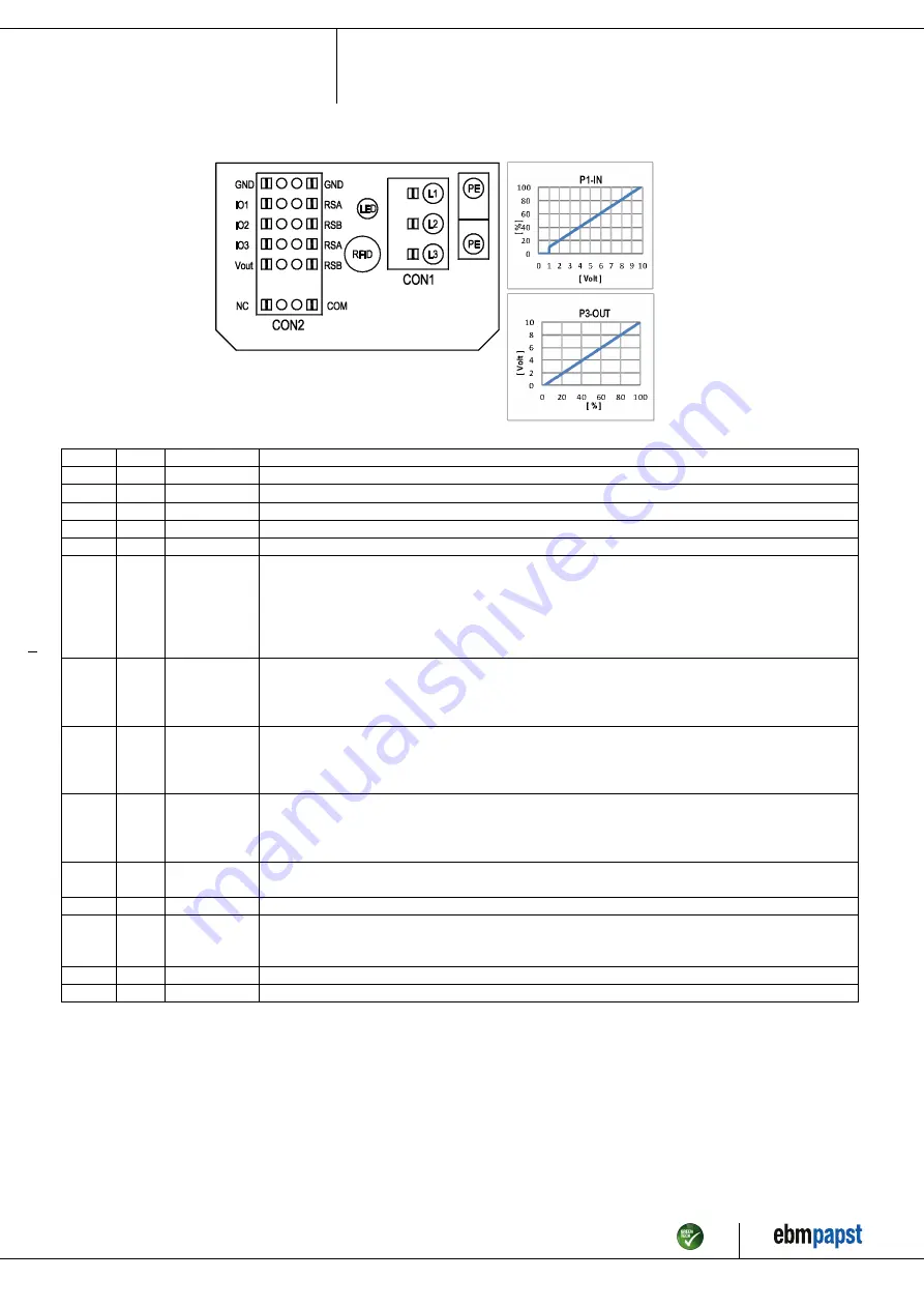
4.5 Connection diagram

No.

Conn.

Designation

Function/assignment

CON1

L1, L2, L3

Power supply, phase, see nameplate for voltage range

PE

PE

Protective earth

CON2

RSA

RS485 interface for MODBUS, RSA; SELV

CON2

RSB

RS485 interface for MODBUS, RSB; SELV

CON2

GND

Reference ground for control interface, SELV

CON2

IO1

Function parameterizable (see “Optional interface functions” table)
Factory setting:
Digital input - high active, function: Disable input, SELV
- inactive: Pin open or applied voltage < 1.5 VDC
- active: applied voltage 3.5-50 VDC
Reset function: Triggering of error reset on change of state from "enabled" to "disabled"

CON2

IO2

Function parameterizable (see “Optional interface functions” table)
Factory setting:
Analog input 0-10 V / PWM, Ri=100 kΩ, function: Set value
Characteristic curve parameterizable (see input characteristic curve P1-IN), SELV

CON2

IO3

Function parameterizable (see “Optional interface functions” table)
Factory setting:
Analog output 0-10 V, max. 5 mA, function: Fan modulation level
Characteristic curve parameterizable (see output characteristic curve P3-OUT), SELV

CON2

Vout

Voltage output 3.3-24 VDC ±5%, Pmax=800 mW, voltage parameterizable
Factory setting: 10 VDC
short-circuit-proof, supply for external devices, SELV
alternatively: 15-50 VDC input for parameterization via MODBUS without line voltage

CON2

COM

Status relay, floating status contact, common connection, contact rating 250 VAC / 2 A (AC1) / min. 10 mA,
reinforced insulation on supply side and on control interface side

CON2

NC

Status relay, floating status contact, break for failure

LED

green: status = good, ready for operation
orange: status = warning
red: status = failure

P1-IN

Input characteristic curve

P3-OUT

Output characteristic curve

Item no. 55777-5-9970 · ENU · Change 200980 · Approved 2018-12-05 · Page 10 / 16

ebm-papst Mulfingen GmbH & Co. KG · Bachmühle 2 · D-74673 Mulfingen · Phone +49 (0) 7938 81-0 · Fax +49 (0) 7938 81-110 · info1@de.ebmpapst.com · www.ebmpapst.com

Summary of Contents for R3G450-PA31-03

Page 1: ...rry out a test run and to perform work on the electrical installation 1 3 Basic safety rules 1 1 3 Basic safety rules The safety hazards associated with the device must be assessed again following ins...

Page 2: ...ling the device in customer equipment Verify that the entire setup is EMC compliant 1 7 Mechanical movement DANGER Rotating device Risk of injury to body parts coming into contact with the rotor or th...

Page 3: ...g the operating instructions Improper use In particular operating the device in the following ways is prohibited and could be hazardous Operating the device in an unbalanced state e g due to dirt depo...

Page 4: ...essure tap k factor 240 not included in scope of delivery 2 Max clearance for screw 20 mm 3 Cable diameter min 4 mm max 10 mm tightening torque 2 0 3 Nm 4 Tightening torque 1 5 0 2 Nm Item no 55777 5...

Page 5: ...n mm inlet ring 45075 2 4013 with pressure tap k factor 240 not included in scope of delivery Item no 55777 5 9970 ENU Change 200980 Approved 2018 12 05 Page 5 16 ebm papst Mulfingen GmbH Co KG Bachm...

Page 6: ...er combination in a standardized measurement setup 3 4 Technical description Weight 21 3 kg Size 450 mm Motor size 150 Rotor surface Painted black Electronics housing material Die cast aluminum Impell...

Page 7: ...e responsibility of the installation engineer or operator owner of the device to ensure if necessary after consultation with the network operator that this device is only connected to a connection poi...

Page 8: ...earth terminal provided on the device The protective earth terminal is located on the housing and provided with a protective earth symbol and a hole 4 2 2 Supply connection and fuses Assignment of sup...

Page 9: ...re ends fan out Seal the terminal box 4 3 3 Cable routing Water must be prevented from reaching the cable gland along the cable NOTE Damage caused by moisture penetration Moisture can penetrate into t...

Page 10: ...eristic curve P1 IN SELV CON2 IO3 Function parameterizable see Optional interface functions table Factory setting Analog output 0 10 V max 5 mA function Fan modulation level Characteristic curve param...

Page 11: ...put Ri 100K characteristic curve parameterizable fPWM 1k 10KHz SELV D159 2 Ain2 4 20mA analog input Ri 125R characteristic curve parameterizable SELV D159 3 Din3 active high digital input not active p...

Page 12: ...operating instructions 4 7 Equivalent circuit diagrams Item no 55777 5 9970 ENU Change 200980 Approved 2018 12 05 Page 12 16 ebm papst Mulfingen GmbH Co KG Bachm hle 2 D 74673 Mulfingen Phone 49 0 793...

Page 13: ...ce from inexpert handling transportation damage and resultant imbalance or be caused by component or structural resonance Speed ranges with excessively high vibration levels and possibly resonant freq...

Page 14: ...wn Ambient temperature too high Reduce the ambient temperature Allow the device to cool down Impermissible operating point e g back pressure too high Correct the operating point Allow the device to co...

Page 15: ...of cables for damage Visual inspection At least every 6 months Replace cables Impeller for wear deposits corrosion and damage Visual inspection At least every 6 months Clean impeller or replace device...

Page 16: ...lating materials Cables and wires Electronic scrap e g circuit boards Only ferrite magnets and not rare earth magnets are used in external rotor motors from ebm papst Mulfingen GmbH Co KG Ferrite magn...

Reviews: