background image

Operating instructions

A3G300-AN02-04

Translation of the original operating instructions

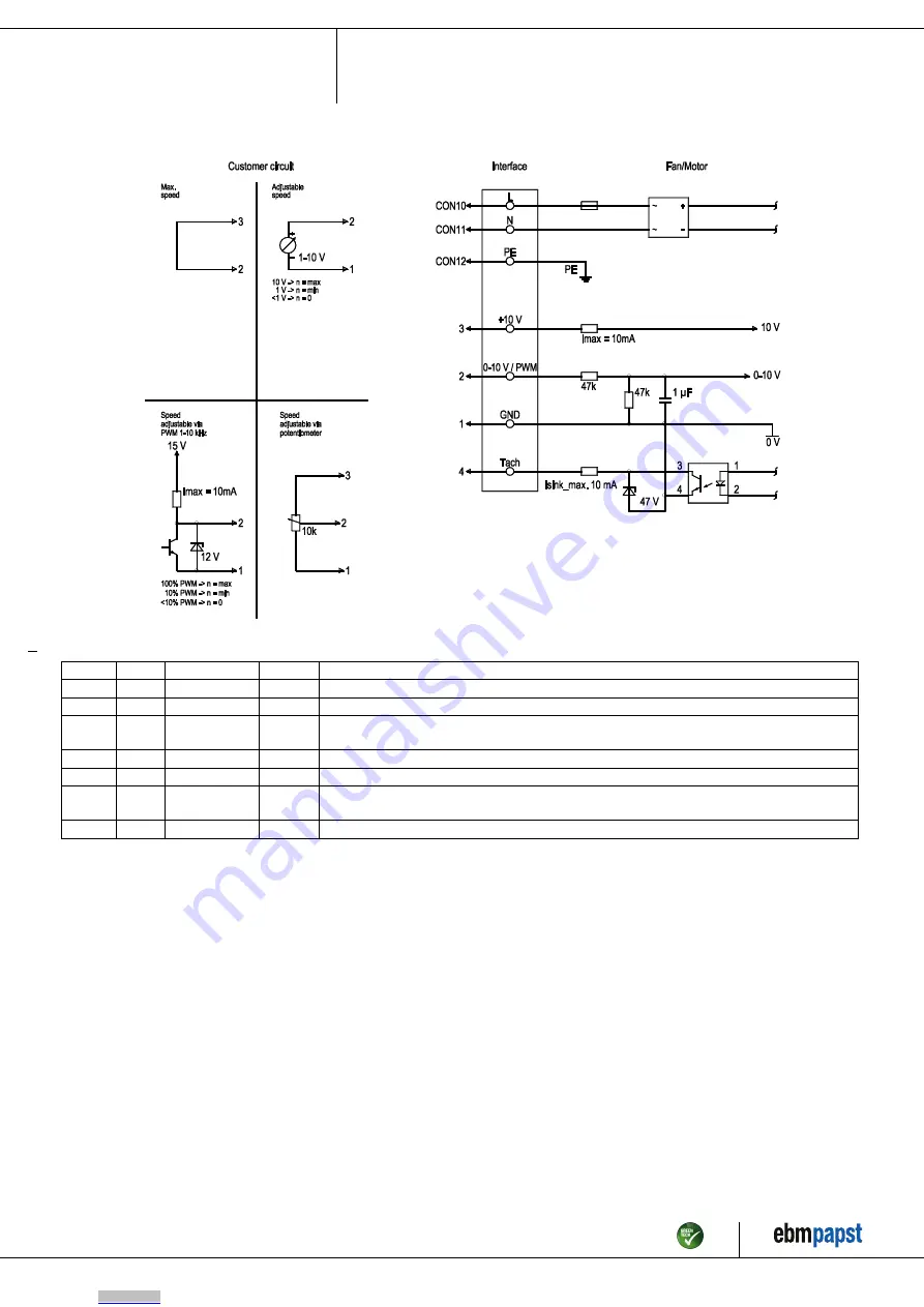
4.4 Connection diagram

Drawing preliminary!

No.

Conn.

Designation

Color

Function/assignment

CON10 L

black

Supply connection, power supply, phase, see nameplate for voltage range

CON11 N

blue

Supply connection, power supply, neutral conductor, see nameplate for voltage range

CON12 PE

green/
yellow

Ground connection

2

0- 10V PWM

yellow

0-10 V / PWM control input, Ri=100 kΩ, SELV

4

Tach

white

Tach output, open collector, 1 pulse per revolution, Isink max = 10 mA, SELV

3

+10 V

red

Fixed voltage output 10 VDC +/-3 %, Imax. 10 mA, short-circuit-proof, power supply for ext.
devices (e.g. pot), SELV

1

GND

blue

Reference ground for control interface, SELV

Item no. 52035-5-9970 · ENU · Change 274579 · Approved 2023-01-10 · Page 8 / 11

ebm-papst Mulfingen GmbH & Co. KG · Bachmühle 2 · D-74673 Mulfingen · Phone +49 (0) 7938 81-0 · Fax +49 (0) 7938 81-110 · info1@de.ebmpapst.com · www.ebmpapst.com

Downloaded from

Arrow.com.

Summary of Contents for A3G300-AN02-04

Page 1: ...bly qualified trained and authorized technical staff Only authorized specialists are permitted to install the device to carry out a test run and to perform work on the electrical installation 1 3 Basi...

Page 2: ...have to be taken by the user NOTE Electrical or electromagnetic interference after installing the device in customer equipment Verify that the entire setup is EMC compliant 1 7 Mechanical movement DA...

Page 3: ...d could be hazardous Operating the device in an unbalanced state e g due to dirt deposits or ice formation Resonant operation operation with severe vibration This also includes vibration transmitted t...

Page 4: ...air flow A 2 Max clearance for screw 10 mm 3 Cable PVC 3G AWG20 3x crimped splices 4 Cable PVC 4x AWG22 4x crimped splices Item no 52035 5 9970 ENU Change 274579 Approved 2023 01 10 Page 4 11 ebm pap...

Page 5: ...ation EU 2019 1781 due to the exception specified in Article 2 2a motors completely integrated into a product 3 4 Technical description Weight 1 96 kg Size 300 mm Motor size 74 Blade material Press fi...

Page 6: ...s have been tightened The fan must not be strained on fastening 4 2 Electrical connection DANGER Voltage on the device Electric shock Always connect a protective earth first Check the protective earth...

Page 7: ...circuit breaker RCCB If the use of a residual current device RCD is required in your installation only pulse current sensitive and or AC DC sensitive residual current devices type F or B are permissib...

Page 8: ...ellow Ground connection 2 0 10V PWM yellow 0 10 V PWM control input Ri 100 k SELV 4 Tach white Tach output open collector 1 pulse per revolution Isink max 10 mA SELV 3 10 V red Fixed voltage output 10...

Page 9: ...operation on and off via power supply Disconnect the device from the power supply When disconnecting be sure to disconnect the ground connection last 5 INTEGRATED PROTECTIVE FEATURES The integrated pr...

Page 10: ...s designed for a service life of 40 000 hours If bearing replacement is necessary after that period contact ebm papst Adapt the maintenance intervals to the actual level of dust exposure 6 2 Safety in...

Page 11: ...us metal e g motor windings Plastics particularly with brominated flame retardants in accordance with marking Insulating materials Cables and wires Electronic scrap e g circuit boards Only ferrite mag...

Reviews: